RPi 3B+ UARTs
There are two types of UART available on the Raspberry Pi - PL011 and mini UART. The PL011 is a capable, broadly 16550-compatible UART, while the mini UART has a reduced feature set.
All UARTs on the Raspberry Pi are 3.3V only - damage will occur if they are connected to 5V systems. An adaptor can be used to connect to 5V systems. Alternatively, low-cost USB to 3.3V serial adaptors are available from various third parties.
Pi Zero, 1, 2 and 3 - two UARTs
The Raspberry Pi Zero, 1, 2, and 3 each contain two UARTs as follows:
| Name | Type |
|---|---|
| UART0 | PL011 |
| UART1 | mini UART |
Primary UART
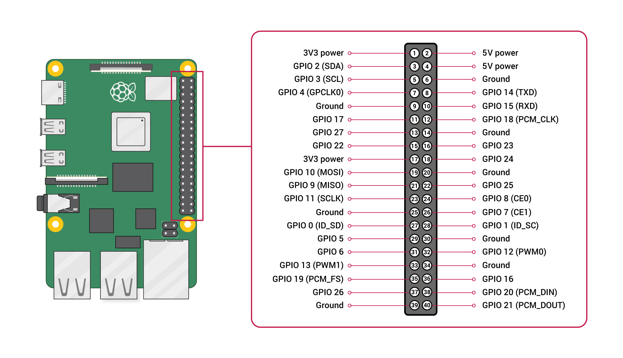
On the Raspberry Pi, one UART is selected to be present on GPIO 14 (transmit) and 15 (receive) - this is the primary UART. By default, this will also be the UART on which a Linux console may be present. Note that GPIO 14 is pin 8 on the GPIO header, while GPIO 15 is pin 10.
Secondary UART
The secondary UART is not normally present on the GPIO connector. By default, the secondary UART is connected to the Bluetooth side of the combined wireless LAN/Bluetooth controller, on models which contain this controller.
Configuration
By default, only UART0 is enabled. The following table summarises the assignment of the first two UARTs:
| Model | first PL011 (UART0) | mini UART |
|---|---|---|
| Raspberry Pi Zero | primary | secondary |
| Raspberry Pi Zero W | secondary (Bluetooth) | primary |
| Raspberry Pi 1 | primary | secondary |
| Raspberry Pi 2 | primary | secondary |
| Raspberry Pi 3 | secondary (Bluetooth) | primary |
| Raspberry Pi 4 | secondary (Bluetooth) | primary |
Note: the mini UART is disabled by default, whether it is designated primary or secondary UART.
Linux devices on Raspberry Pi OS:
| Linux device | Description |
|---|---|
/dev/ttyS0 |
mini UART |
/dev/ttyAMA0 |
first PL011 (UART0) |
/dev/serial0 |
primary UART |
/dev/serial1 |
secondary UART |
Note: /dev/serial0 and /dev/serial1 are symbolic links which point to either /dev/ttyS0 or /dev/ttyAMA0.
Mini UART and CPU core frequency
In order to use the mini UART, you need to configure the Raspberry Pi to use a fixed VPU core clock frequency. This is because the mini UART clock is linked to the VPU core clock, so that when the core clock frequency changes, the UART baud rate will also change. The enable_uart and core_freq settings can be added to config.txt to change the behaviour of the mini UART. The following table summarises the possible combinations:
| Mini UART set to | core clock | Result |
|---|---|---|
| primary UART | variable | mini UART disabled |
| primary UART | fixed by setting enable_uart=1 |
mini UART enabled, core clock fixed to 250MHz, or if force_turbo=1 is set, the VPU turbo frequency |
| secondary UART | variable | mini UART disabled |
| secondary UART | fixed by setting core_freq=250 |
mini UART enabled |
The default state of the enable_uart flag depends on which UART is the primary UART:
| Primary UART | Default state of enable_uart flag |
|---|---|
| mini UART | 0 |
| first PL011 (UART0) | 1 |
UARTs on CM3
There are 2 UARTs module on CM3 For more information, you can read pin description. If you want to use 2 UARTs. You can edit /boot/config.txt
#UART0 aka ttyAMA0 pin 14,15
enable_uart=1
dtoverlay=pi3-disable-bt
dtparam=uart0=on

#UART1 aka ttyS0
dtoverlay=uart1,txd1_pin=32,rxd1_pin=33
Enabling Serial Communication On RPi
Enable using raspi-config interface options, then disable linux serial login but enable hardware serial.
Serial Communication Examples
Communication Using Screen (Terminal)
-
connect the serial port on Mac Using Cool Term:
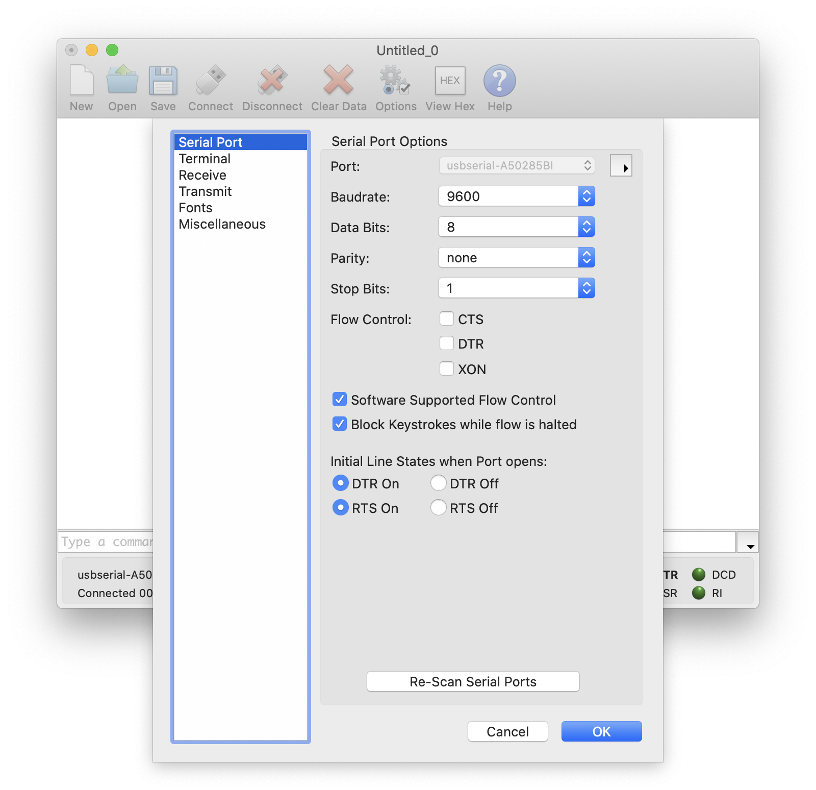
-
Connect the Serial Port on RPi using
screenscreen /dev/serial0 9600
Just incase other programming programs are using the port ,we should got the port :
sudo lsof /dev/serial
We can then kill the program using that serial port.
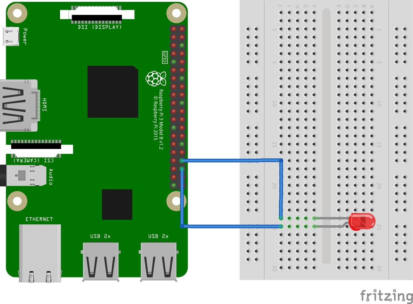
Example 1: Blinking an LED Using C++ (WiringPI)
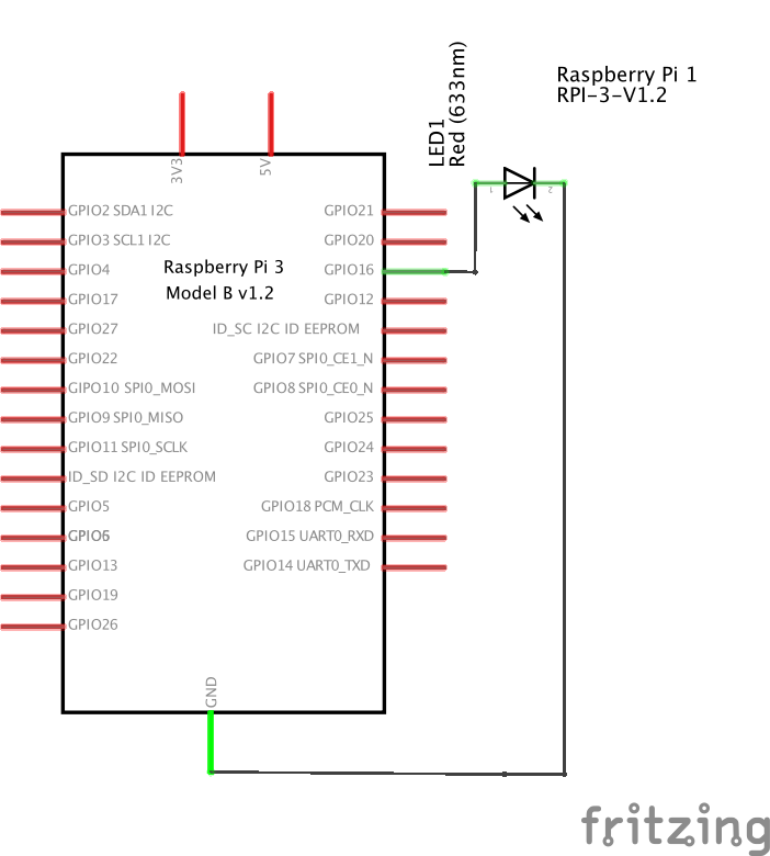
#include <wiringPi.h>

int main(void)
{
    wiringPiSetupGpio();
    pinMode(16, OUTPUT);
    for (;;)
    {
        digitalWrite(16, HIGH);
        delay(500);
        digitalWrite(16, LOW);
        delay(500);
    }
    return 0;
}
To build the code :
gcc -Wall -o blink blink.cpp -lwiringPi
gcc -Wall option flag
gcc -Wall enables all compiler’s warning messages. This option should always be used, in order to generate better code.
$ gcc -Wall [options] [source files] [object files] [-o output file]
gcc -Wall myfile.c -o myfile
Example 2: Receiving Single Characters
In very many cases all that is needed is to send a single character to the RPi . Between the upper and lower case letters and the numeric characters there are 62 options. For example you could use ‘F’ for forward, ‘R’ for reverse and ‘S’ for stop.
Code to receive a single character is as simple as this:
#include <stdio.h>
#include <wiringPi.h>
#include <wiringSerial.h>

int main()
{
    // intializing some variables
    __uint8_t newData = 0;
    char receivedChar;

    int fd;
    if (wiringPiSetupGpio() < 0)
    {
        return 1; // setup gpio failure.
    }
    if ((fd = serialOpen("/dev/serial0", 9600)) < 0)
    {
        return 1; //failed to open the serial port
    }
    printf("Serial Communication Start:\n");

    // loop
    for (;;)
    {
        // receive data
        if (serialDataAvail(fd) > 0)
        {
            receivedChar = serialGetchar(fd);
            newData = 1;
        }

        // show data
        if (newData)
        {
            printf("This just in ...");
            printf("%c", receivedChar);
            printf("\n");
            newData = 0;
        }
    }
    // loop end

    serialClose(fd);
    return 0;
}
Then build and run the code ;
gcc -Wall -o recvsc recvsinglec.c -lwiringPi
Code Result;
Example 2: Receiving several characters from the Serial Monitor.
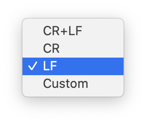
If you need to receive more than a single character from the Serial Monitor (perhaps you want to input people’s names) you will need some method of letting the RPi know when it has received the full message. The simplest way to do this is to set the line-ending to newline.
This is done with the box at the bottom of the Cool Term Options. You can choose between “No line ending”, “Newline”, “Carriage return” and “Both NL and CR”. When you select the “Newline” option a new-line character (‘\n’) is added at the end of everything you send.
#include <stdio.h>
#include <wiringPi.h>
#include <wiringSerial.h>

int main()
{
    // intializing some variables
    const __uint8_t numChars = 32;
    char receivedChars[numChars]; // an array to store the received data;
    __uint8_t newData = 0;

    int fd;
    if (wiringPiSetupGpio() < 0)
    {
        return 1; // setup gpio failure.
    }
    if ((fd = serialOpen("/dev/serial0", 9600)) < 0)
    {
        return 1; //failed to open the serial port
    }
    printf("Serial Communication Start:\n");

    // loop
    for (;;)
    {
        // receive data with a marker
        static __uint8_t ndx = 0;
        char endMarker = '\n';
        char rc;
        while (serialDataAvail(fd) > 0 && !newData)
        {
            rc = serialGetchar(fd);
            if (rc != endMarker)
            {
                receivedChars[ndx] = rc;
                ndx++;
                if (ndx >= numChars)
                {
                    ndx = numChars - 1;
                }
            }
            else
            {
                receivedChars[ndx] = '\0'; //terminate the string
                ndx = 0;
                newData = 1;
            }
        }

        // show data
        if (newData)
        {
            printf("This just in ...");
            printf("%s", receivedChars);
            printf("\n");
            newData = 0;
        }
    }
    // loop end

    serialClose(fd);
    return 0;
}
gcc -Wall -o recvmc recvmultc.c -lwiringPi
This version of the program reads all the characters into an array until it detects the Newline character as an end marker.