A copy-paste material for satellite communications
Intro
How satellites work
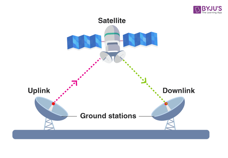
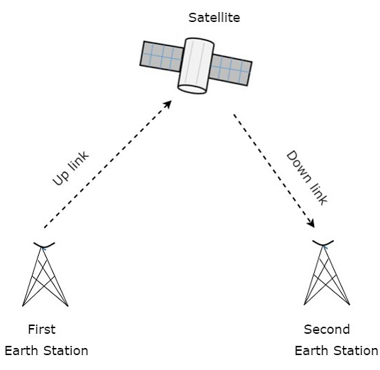
A communication satellite is nothing but a microwave repeater station in space.
A repeater is a circuit, which increases the strength of the received signal and then transmits it. But, this repeater works as a transponder. That means, it changes the frequency band of the transmitted signal from the received one.
The frequency with which, the signal is sent into the space is called as Uplink frequency. Similarly, the frequency with which, the signal is sent by the transponder is called as Downlink frequency.

Satellite communication - transponders
Транспондер
The subsystem, which ==provides the connecting link between transmitting and receiving antennas of a satellite is known as Transponder==.
Transponder performs the functions of both transmitter and receiver (Responder) in a satellite. Hence, the word ‘Transponder’ is obtained by the combining few letters of two words, ==Transmitter (Trans) and Responder (ponder)==.
Block diagram of transponder
Transponder mainly performs two functions :
- Amplifying the received input signal
- Translates the frequency of it
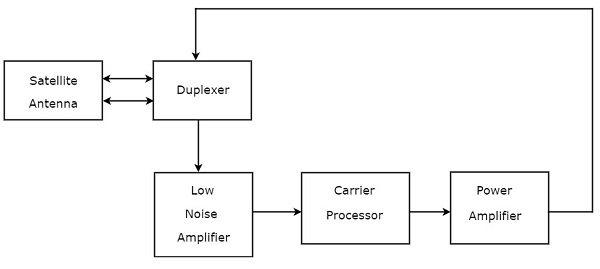
- Duplexer is a two-way microwave gate. It receives uplink signal from the satellite antenna and transmits downlink signal to the satellite antenna.
- Low Noise Amplifier (LNA) amplifies the weak received signal.
- Carrier Processor performs the frequency down conversion of received signal (uplink). This block determines the type of transponder.
- Power Amplifier amplifies the power of frequency down converted signal (down link) to the required level.
Duplexer :


Low Noise Amplifier:
Power amplifier :

Types of Transponders
Bent Pipe Transponders
Bent pipe transponder receives microwave frequency signal. It converts the frequency of input signal to RF frequency and then amplifies it.
Bent pipe transponder is also called as repeater and conventional transponder. It is suitable for both analog and digital signals.
Regenerative Transponders
Regenerative transponder performs the functions of Bent pipe transponder. i.e., frequency translation and amplification. In addition to these two functions, Regenerative transponder also performs the demodulation of RF carrier to baseband, regeneration of signals and modulation.
Regenerative transponder is also called as Processing transponder. ==It is suitable only for digital signals==.
The main advantages of Regenerative transponders are improvement in ==Signal to Noise Ratio (SNR)== and have more flexibility in implementation.
Earth Segment Subsystem
In general, earth stations receive the baseband signals in one of the following forms. Voice signals and video signals either in analog form or digital form.
Initially, the analog modulation technique, named FM modulation is used for transmitting both voice and video signals, which are in analog form.
Later, digital modulation techniques, namely ==Frequency Shift Keying (FSK)== and ==Phase Shift Keying (PSK)== are used for transmitting those signals. Because, both voice and video signals are used to represent in digital by converting them from analog.
Block Diagram of Earth Station
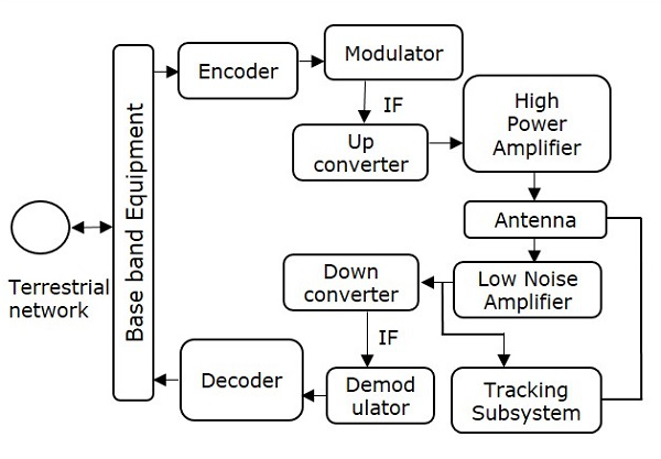
Transmitter
The binary (digital) information enters at base band equipment of earth station from terrestrial network. Encoder includes error correction bits in order to minimize the bit error rate.
In satellite communication, the ==Intermediate Frequency (IF)== can be chosen as 70 MHz by using a transponder having bandwidth of 36 MHz. Similarly, the IF can also be chosen as 140 MHz by using a transponder having bandwidth of either 54 MHz or 72 MHz.
Up converter performs the frequency conversion of modulated signal to higher frequency.
This signal will be amplified by using High power amplifier. The earth station antenna transmits this signal.
Receiver
During reception, the earth station antenna receives downlink signal. This is a low-level modulated RF signal.
In general, the received signal will be having less signal strength. So, in order to amplify this signal, ==Low Noise Amplifier (LNA)== is used. Due to this, there is an improvement in Signal to Noise Ratio (SNR) value.
RF signal can be down converted to the Intermediate Frequency (IF) value, which is either 70 or 140 MHz. Because, it is easy to demodulate at these intermediate frequencies.
The function of the decoder is just opposite to that of encoder. So, the decoder produces an error free binary information by removing error correction bits and correcting the bit positions if any.
This binary information is given to base band equipment for further processing and then delivers to terrestrial network.