
1 Onboard Computer
The on-board computer (hereafter referred to as the OBC) is an integral part of the spacecraft, also the main computing unit of the UniSat. The main load falls on the OBC, and all nodes and subsystems must be controlled, executed algorithms embedded in the On-board computer. In the purpose of education usage, the on-board computer must also perform the functions of an interactive reference document or book, development environment and communication center for the other subsystems.
In addition to those, On board computer (OBC) is the major brain of the satellite, responsible for all core functions, like collecting the system data, logging, error handling, data monitoring, and etc.
Here on the OBC, we have two cameras on OBC, one as a general RPi camera that responsible for capturing beautiful space images while the other is responsible for video recordings.
The capturing task (both imaging and video recording) is a software designed task that runs among almost all the satellite life time in a cycled period.
1.1 Technical Tasks and Requirements for the OBC
The technical task / requirement for the on-board computer is presented in a tabular form below:
| Main Computing Power Provider | Memory | Physical Interfaces | Network Connection | Dimensions |
|---|---|---|---|---|
| Raspberry Pi CM3/CM3 Lite (4C/1.4 Ghz, 1GB RAM) |
4 GB eMMC 64 GB MicroSD/TF |
- USB2.0 — 2 - RS485 — 1 - I2C — 1 - CSI — 2 - UART — 1* |
WiFi 802.11 b\g\n (KZ) |
10*10*0.46 |
1.2 Technical Specifications of the UniSat OBC
- Processor: BCM2837
- Number of CPU Cores: 4
- CPU Architecture: ARM
- CPU Core: ARMv8
- Random Access Memory (RAM): 1GB
- Memory: 64 GB microSD
- Non-volatile Memory: 64Kbit
- Wireless Interface: WiFi
- Total USB interfaces: 2
- Total Camera Interfaces : 2 CSI
- Physical Interface for Connecting Devices: mini-PCI
- Electrical Interfaces for Communication with hardware devices: I2C and RS485
1.3 OBC Hardware Development
1.3.1 OBC Hardware Overview
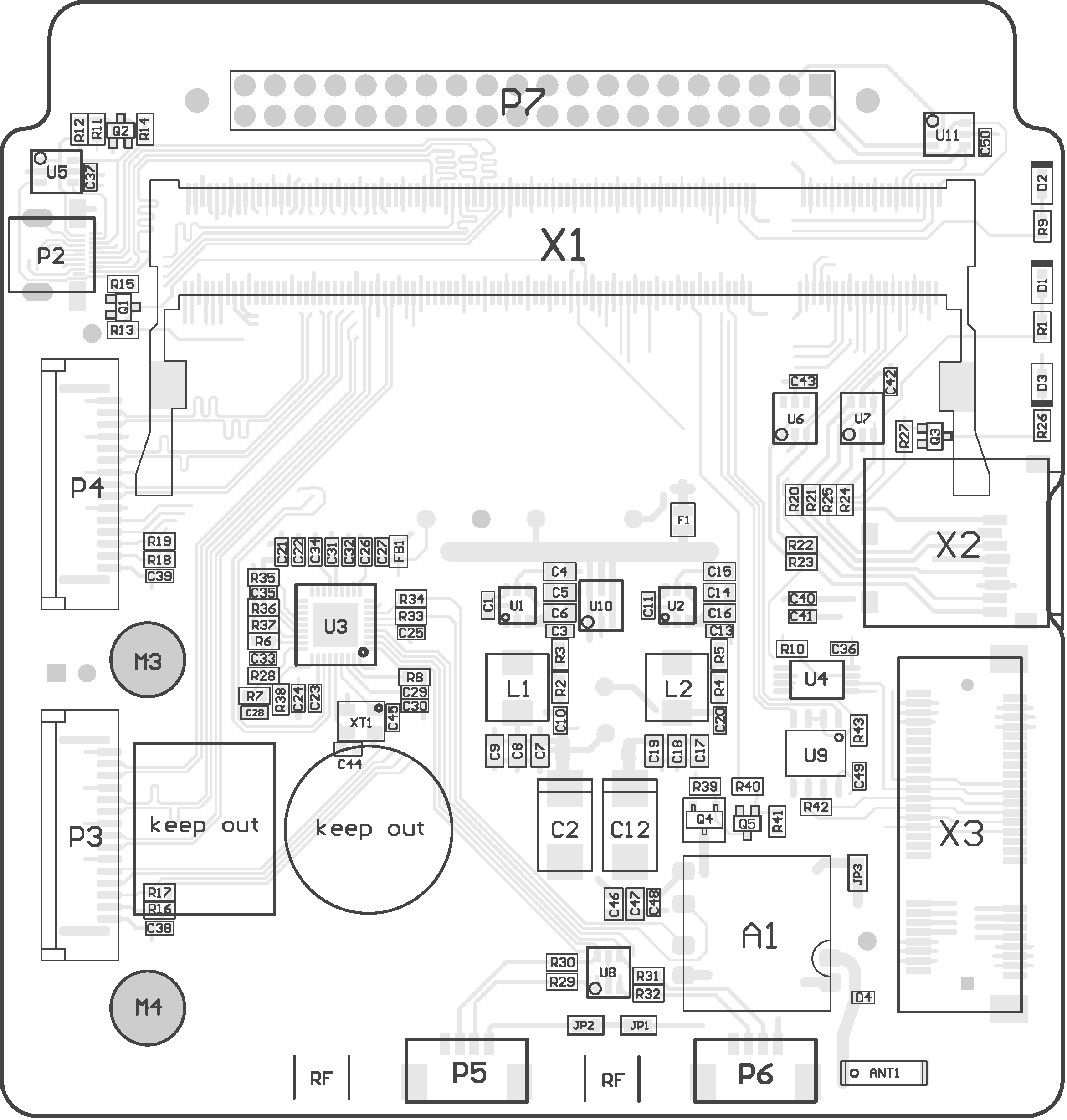
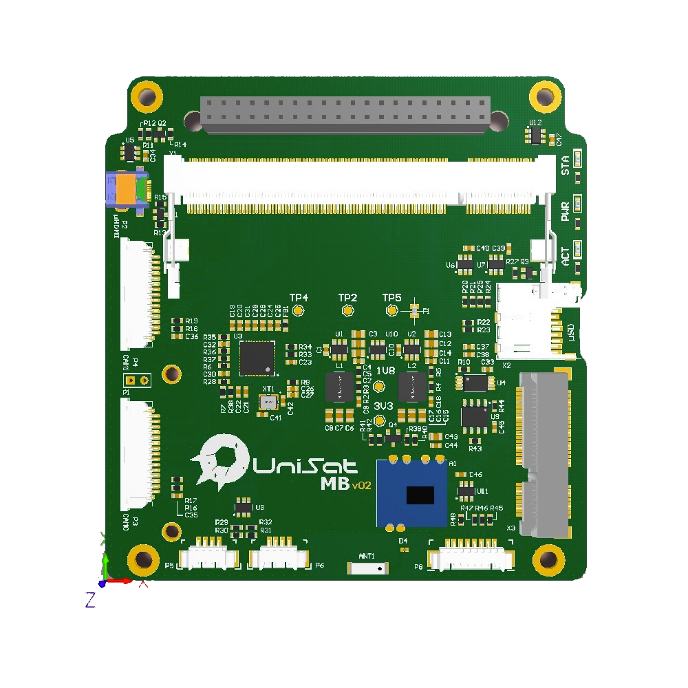
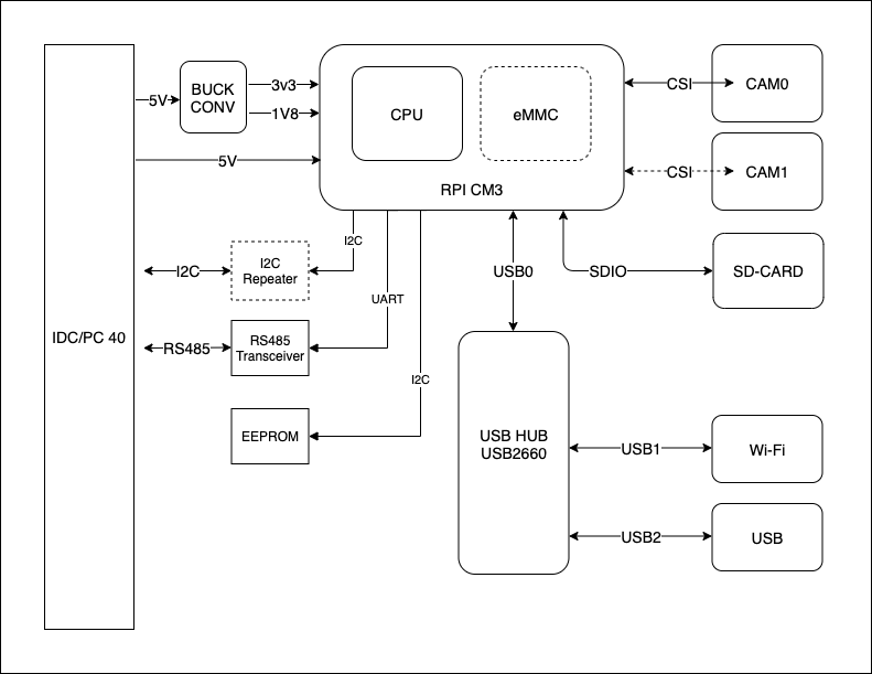
As we can see from the Pic1.3.1 and Pic1.3.2 the UniSat OBC Hardware itself includes several sub parts as OBC power supply, OBC IO, OBC Video (HDMI), OBC Camera, OBC Storage, OBC USB, OBC RS485 PCB designs. We will discuss all of them one after one.
One of the main part of the UniSat is OBC, and one of the key concept and process in the OBC hardware development is the printed circuit board or PCB development.
Printed circuit board is the most common name but may also be called “printed wiring boards” or “printed wiring cards”. Before the advent of the PCB circuits were constructed through a laborious process of point-to-point wiring. This led to frequent failures at wire junctions and short circuits when wire insulation began to age and crack. A significant advance was the development of wire wrapping, where a small gauge wire is literally wrapped around a post at each connection point, creating a gas-tight connection which is highly durable and easily changeable. As electronics moved from vacuum tubes and relays to silicon and integrated circuits, the size and cost of electronic components began to decrease. Electronics became more prevalent in consumer goods, and the pressure to reduce the size and manufacturing costs of electronic products drove manufacturers to look for better solutions. Thus was born the PCB.
PCB is an acronym for printed circuit board. It is a board that has lines and pads that connect various points together. In the picture above, there are traces that electrically connect the various connectors and components to each other. A PCB allows signals and power to be routed between physical devices. Solder is the metal that makes the electrical connections between the surface of the PCB and the electronic components. Being metal, solder also serves as a strong mechanical adhesive.
1.3.2 Learning the Basics of PCB Design
1.3.2.1 Composition
A PCB is sort of like a layer cake or lasagna- there are alternating layers of different materials which are laminated together with heat and adhesive such that the result is a single object.
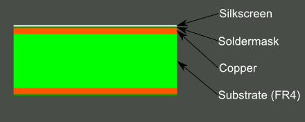
The base material, or substrate, is usually fiberglass. Historically, the most common designator for this fiberglass is “FR4”. This solid core gives the PCB its rigidity and thickness. There are also flexible PCBs built on flexible high-temperature plastic (Kapton or the equivalent).
UniSat PCB used industrial substrate material for best performance of the spacecraft and stability. The next layer is a thin copper foil, which is laminated to the board with heat and adhesive. On common, double sided PCBs, copper is applied to both sides of the substrate. In lower cost electronic gadgets the PCB may have copper on only one side. When we refer to a double sided or 2-layer board we are referring to the number of copper layers (2) in our lasagna. This can be as few as 1 layer or as many as 16 layers or more. UniSat PCBs uses single sided PCB designed, which is not very space efficient but easy to design and use, best choice for educational projects.
The layer on top of the copper foil is called the soldermask layer. This layer gives the PCB its green (or, at some of the AlfaSat earlier boards, blue) color. It is overlaid onto the copper layer to insulate the copper traces from accidental contact with other metal, solder, or conductive bits. This layer helps the user to solder to the correct places and prevent solder jumpers.
1.3.2.2 PCB Designing Software
Altium Designer is the software that used to create beautiful, powerful and functional UniSat PCBs. Though it is a commercial software, you can download a free trial version and complete your non-commercial purpose (as Educational projects like UniSat) during the period. More detailed informations can be found at allium designer’s official website (https://altium.com/altium-designer) and won’t mentioned longer here.
Learning allium designer is a simple process as learning other PC softwares like Word, Excel et.c and won’t be hard. Here we also left the course contents on a course content file to keep this documentation much simple and focused.
1.3.3 Electrical Components/ Circuits Used to assemble the UniSat OBC
While Assembling the real hardware, it is very important that you can differ and use different electrical parts and identify them with their specific characteristics. Here in below, in the table 1.3.3.1 we listed all the electrical components that used to assemble the OBC hardware.
| No. | Name | Description | Designator | Quantity |
|---|---|---|---|---|
| 1 | 100n | CAP CER 0.1UF 16V X7R 0603 | C1,C3,C10,C11,C13,C20,C22,C23,C24,C25,C26,C27,C28,C29,C31,C33,C34,C35 | 18 |
| 2 | 220u | Tantalum Capacitors 220uF 6.3V CASE-D_7343 RoHS | C2,C12 | 2 |
| 3 | 10u | CAP CER 10UF 16V X7R 0805 | C4,C5,C14,C15 | 4 |
| 4 | 22u | CAP CER 22UF 16V X5R 0805 | C6,C7,C8,C9,C16,C17,C18,C19 | 8 |
| 5 | 1u | CAP CER 1UF 16V X7R 0603 | C21,C30,C32 | 3 |
| 6 | LTST-C190GKT | LED GREEN CLEAR CHIP SMD 0603 | D1 | 1 |
| 7 | MH1608-601Y | FERRITE BEAD 600R@100MHz 0603 for Power Line, 1000mA | FB1 | 1 |
| 8 | 2.2uH | FIXED IND 2.2UH 5.5A 36 MOHM SMD | L1L2 | 2 |
| 9 | 9774030151R | RND STANDOFF M2.5X0.45 STEEL 3MM | M3,M4 | 2 |
| 10 | 913-2664 | RASPBERRY PI CAMERA MODULE V2 | M6 | 1 |
| 11 | 1k | RES SMD 1K OHM 5% 1/10W 0603 | R1 | 1 |
| 12 | 33.2k | RES 33.2K OHM 1% 1/10W 0603 | R2 | 1 |
| 13 | 10.0k | RES 10K OHM 1% 1/10W 0603 | R3,R5 | 2 |
| 14 | 13.7k | RES 13.7K OHM 1% 1/10W 0603 | R4 | 1 |
| 15 | 100k | RES 100K OHM 1% 1/10W 0603 | R6 | 1 |
| 16 | 12k | RES SMD 12K OHM 1% 1/10W 0603 | R8 | 1 |
| 17 | TPS565201DDCR | Buck Switching Regulator IC Positive Adjustable 0.76V 1 Output 5A SOT-23-6 Thin, TSOT-23-6 | U1,U2 | 2 |
| 18 | USB2514B/M2 | IC HUB CTLR 4PORT USB 2.0 HS 36S | U3 | 1 |
| 19 | 1717254-4 | CONN SKT SODIMM 200POS R/A SMD | X1 | 1 |
| 20 | CM3+/LITE | RASPBERRY PI COMPUTE 3+ LITE | M1 | 1 |
| 21 | FishEye | RASPBERRY PI CAMERA MODULE V2 | M5 | 1 |
| 22 | SDCG2/64GB | MemoryCard Class 10, 64GB | M2 | 1 |
1.3.4 Electrical/ PCB Design of OBC Power Supply
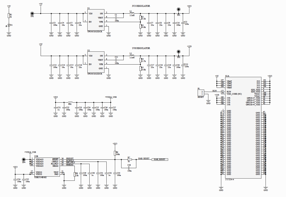
As we can see from the Pic1.3.4.1, UniSat OBC requires 5V/2A power, and powered by the UniSat 40 pin Bus, as is shown in the Pic1.3.4.2 and Table 1.3.4.1 below:
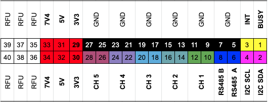
| Channel | Connection | Voltage | Current |
|---|---|---|---|
| CH1 | OBC | 5V | 2A |
| CH2 | TRX | 7V4 | 1A |
| CH3 | SBRD | 3V3 | 500mA |
| CH4 | PAY | 3V3 | 500mA |
| CH5 | TOP | 5V | 1.2A |
1.3.5 Electrical/ PCB Design of OBC IO pins
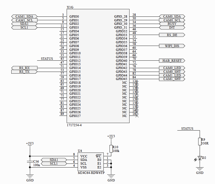
The Raspberry Pi compute module 3B Lite on the OBC, is connected with several physical interfaces as is shown in the Pic1.3.5, and perform it’s hardware functionalities as is shown in the Table 1.3.5 below:
| No. | GPIO | Port | Functions | Description |
|---|---|---|---|---|
| 1 | GPIO0 | 3 | CAM1_SDA | Camera 1 Data Signal |
| 2 | GPIO1 | 5 | CAM1_SCL | Camera 1 Serial Signal |
| 3 | GPIO2 | 9 | SDA1 | I2C Bus Data Signal |
| 4 | GPIO3 | 11 | SCL1 | I2C Bus Clock Signal |
| 5 | GPIO14 | 51 | RS_RX | Serial UART Receive Line |
| 6 | GPIO15 | 53 | RS_TX | Serial UART Transmission Line |
| 7 | GPIO28 | 28 | CAM0_SDA | Camera 0 Data signal |
| 8 | GPIO29 | 30 | CAM0_SCL | Camera 0 Clock Signal |
| 9 | GPIO33 | 48 | RS_DE | RS485 Driver Enable |
| 10 | GPIO36 | 58 | WIFI_DS | WiFi Diable Signal |
| 11 | GPIO40 | 70 | HAB_RESET | USB Hub Reset Signal |
OBC GPIO Pin configurations is significantly important for further software development, wrong hardware pin configuration may also cause hardware damage.
1.3.6 Electrical/ PCB Design of OBC RS485
Each of UniSat subsystems are connected with each other through RS485 Bus. That’s only and main communication bus among the whole UniSat system, so it is extremely important.
Usually , RS485 has 4 important pinouts, Data A, Data B, Driver Enable pin RS_DE and a ground pin GND.
As we have already mentioned in the Table 1.3.5, GPIO 14 and GPIO 15 of the Raspberry Pi is connected to the port 51,53 which functions as the UART receiving and transmitting pins.
To perform the RS485 functionality, they then connected with a RS485—UART converter as is shown in the Pic1.3.6.1 and Pic1.3.6.2 below:
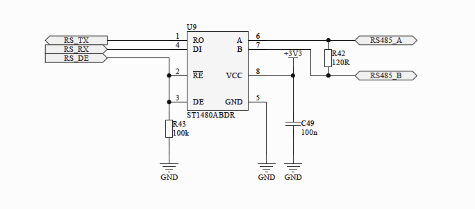
In addition to this, RS_DE is connected to GPIO33, Port 48, should be noticed and remembered as we will use it to control the RS485 Transmission later in software development process.
1.4 OBC software Development
Developing Software for OBC is as easy as developing software for a Linux PC, as we run a common Linux/Unix kernel in the On-board System Raspberry Pi compute Model, the tiny yet very powerful computer.
As we can see from the Pic 1.4.1, OBC exists as one of the subsystem of the UniSat integrated hardware, and functions as the brain.
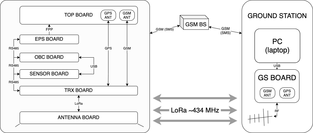
UniSat is a nano-satellite which consists from several main hardware parts, including the TOP BOARD, EPS BOARD, OBC BOARD, SENSOR BOARD (AlfaSense), TRX BOARD, ANTENNA BOARD, as shown in the Pic1.4.1.
1.4.1 Recognizing OBC for Software Development
Building a software or software system for OBC simply means building a software system to monitor, control the linux operating system as well as the OBC peripherals that are connected with OBC using various physical interfaces as shown in the Pic1.4.1.1 and Table 1.4.1 below:
| No. | Component | Action | Description | Priority |
|---|---|---|---|---|
| 1 | CPU | CPU_STAT | Check the RPi CPU status | High |
| 2 | CPU | CPU_TEMP | Check the RPi ARM Core Temperature | High |
| 3 | CPU | CPU_USG | Check CPU usage | High |
| 4 | CPU | CPU_VOLT | Check CPU Consuming Voltage | High |
| 5 | eMMC | MEM | Check available operating memory | High |
| 6 | microSD | MEM_SD | Check sd card usage | High |
| 7 | I2C | I2C Stat | Check I2C device Status | High |
| 8 | I2C | I2C_GET | Get I2C information (from SBRD) | High |
| 9 | CAM0 | CAM0_GET | Get image and video from camera 0 | High |
| 10 | CAM1 | CAM1_GET | Get image and video from camera 1 | High |
| 11 | SYS | SYS_SCHED | System Scheduled Tasks | Very High |
| 12 | RS485 | RS_CHECK | Check RS485 Communication Bus | Very High |
| 13 | RS485 | RS_Log | Log RS485 messages | Very High |
| 14 | RS485 | RS_Get | Get SBRD conditions from RS485 | Very High |
| 15 | SYS | SYS_BACKUP | Back up System log | Very High |
| 16 | SYS | SYS_LOG_BK | Black Box | Very High |
| 17 | USB | USB_QUERRY | Get SBRD Data from USB UART | Very High |
| 18 | SYS | WIFI_CK | Check Wifi Status | Low |
| 19 | CPU | CPU_FREQ | Check CPU frequency | Low |
| 20 | SYS | RESET | Reset The System | Never |
1.4.2 Preparing Software Development Environment for UniSat OBC
1.4.2.1 Git and Github
Git and Github is essential and very useful while working with a team. UniSat projects are hosted at Github or Bitbucket, which also a git based source code repository platform.
To work with Git/Github we need to do several steps as below:
-
Register at https://github.com
-
Install Git
-
Mac OS
brew install git -
Linux/Unix
sudo apt install git -y -
Windows
Download .exe installer from https://git-scm.org and follow install instructions.
-
-
Configure Git
Open Terminal and configure personal info as :
git config --global user.name "Your Name" git config --global user.mail "Your Email Address" -
Add SSH to Github/Bitbucket
ls -al ~/.ssh
ssh-keygen -t rsa -b 4096 -C "Your Email Address"
eval "$(ssh-agent -s)"
ssh-add -K ~/.ssh/id_rsa
1.4.2.2 GCC
GCC is an integrated distribution of compilers for several major programming languages. These languages currently include C, C++, Objective-C, Objective-C++, Java, Fortran, and Ada. … The goal is to make the system interpret the C code and convert it into a machine language that the system understands.
UniSat software development requires GCC to compile C/C++ based codes.
To install GCC:
-
On Mac OS:
brew install gcc -
Linux:
sudo apt install gcc -
Windows:
Download MinGW, a contraction of “Minimalist GNU for Windows”, is a minimalist development environment for Windows, from http://www.mingw.org/ and follow the install instructions.
1.4.2.3 Python
Python is an easy to learn but ver powerful programming language, it is the default programming language for raspberry pi on UniSat OBC. If you run Linux, Python should already there, if you run other systems rather than linux, follow the steps below to install it (We use Python version 3 at UniSat Projects):
-
Mac OS:
brew install python3 -
Windows:
Download Python 3.x installer from Python official site https://python.org and follow the instructions.
1.4.3 Get OBC CPU and GPU information Using vcgencmd
vcgencmd is a command line utility that can get various pieces of information from the VideoCore GPU on the Raspberry Pi.
Usage
To get a list of all the commands that vcgencmd supports, type vcgencmd commands.
Some of the more useful commands are described below.
Commands
-
measure_temp: Returns the temperature of the SoC as measured by the on-board temperature sensor.
-
measure_clock [clock]: This returns the current frequency of the specified clock. The options are:
clock Description arm ARM cores core VC4 scaler cores H264 H264 block isp Image Signal Processor v3d 3D block uart UART pwm PWM block (analogue audio output) emmc SD card interface pixel Pixel valve vec Analogue video encoder hdmi HDMI dpi Display Peripheral Interface e.g.
vcgencmd measure_clock arm -
measure_volts [block]: Displays the current voltages used by the specific block.
block Description core VC4 core voltage sdram_c SDRAM Core Voltage sdram_i SDRAM I/O voltage sdram_p SDRAM Phy Voltage -
otp_dump: Displays the content of the One Time Programmable (OTP) memory, which is part of the SoC. These are 32 bit values, indexed from 8 to 64.
-
get_mem type: Reports on the amount of memory allocated to the ARM cores
vcgencmd get_mem armand the VC4vcgencmd get_mem gpu. -
codec_enabled [type]: Reports whether the specified CODEC type is enabled. Possible options for type are AGIF, FLAC, H263, H264, MJPA, MJPB, MJPG, MPG2, MPG4, MVC0, PCM, THRA, VORB, VP6, VP8, WMV9, WVC1.(Some of those are used on OBC Cameras)
-
mem_oom: Displays statistics on any Out Of Memory events occuring in the VC4 memory space.
-
mem_reloc_stats: Displays statistics from the relocatable memory allocator on the VC4.
-
read_ring_osc: Returns the curent speed voltage and temperature of the ring oscillator.
1.4.4 Preparing Camera Modules
To use the camera modules first we have to enable the camera, to do these,Go to the main menu and open the Raspberry Pi Configuration tool.
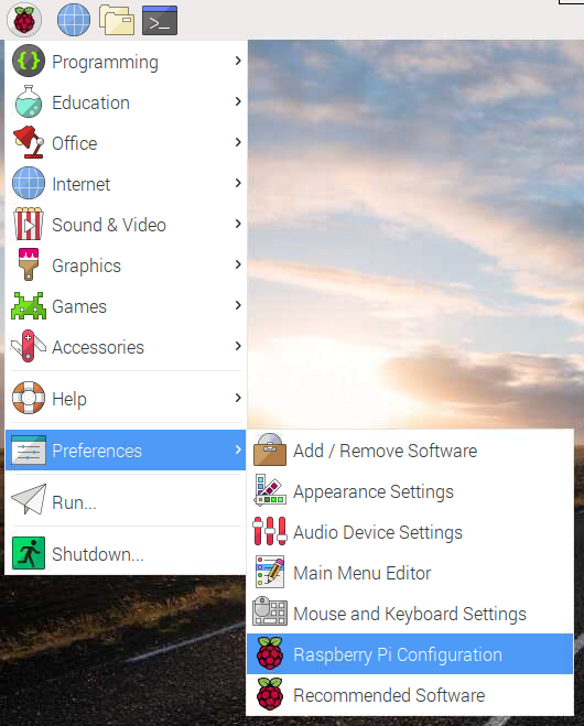
Select the Interfaces tab and ensure that the camera is enabled:

Then Reboot the System.
By default the Raspberry Pi compute module 3b+ lite on UniSat OBC, supports only one camera, but we need to use at least two of them. Due to this, we have to reconfigure the linux device tree to enable our second cable.
To do this, we simply have to download the dt-blob file from the UniSat USK repository in Github, and then copy it to the /boot directory of the RPi.
Then we have to replace the config.txt file with this:
# For more options and information see
# http://rpf.io/configtxt
# Some settings may impact device functionality. See link above for details

# uncomment if you get no picture on HDMI for a default "safe" mode
#hdmi_safe=1

# uncomment this if your display has a black border of unused pixels visible
# and your display can output without overscan
disable_overscan=1

# uncomment the following to adjust overscan. Use positive numbers if console
# goes off screen, and negative if there is too much border
#overscan_left=16
#overscan_right=16
#overscan_top=16
#overscan_bottom=16

# uncomment to force a console size. By default it will be display's size minus
# overscan.
#framebuffer_width=1280
#framebuffer_height=720

# uncomment if hdmi display is not detected and composite is being output
hdmi_force_hotplug=1

# uncomment to force a specific HDMI mode (this will force VGA)
hdmi_group=2
hdmi_mode=82

# uncomment to force a HDMI mode rather than DVI. This can make audio work in
# DMT (computer monitor) modes
#hdmi_drive=2

# uncomment to increase signal to HDMI, if you have interference, blanking, or
# no display
#config_hdmi_boost=4

# uncomment for composite PAL
#sdtv_mode=2

#uncomment to overclock the arm. 700 MHz is the default.
#arm_freq=800

# Uncomment some or all of these to enable the optional hardware interfaces
dtparam=i2c_arm=on
#dtparam=i2s=on
dtparam=spi=on

# Uncomment this to enable infrared communication.
#dtoverlay=gpio-ir,gpio_pin=17
#dtoverlay=gpio-ir-tx,gpio_pin=18

# Additional overlays and parameters are documented /boot/overlays/README

# Enable audio (loads snd_bcm2835)
dtparam=audio=on

[pi4]
# Enable DRM VC4 V3D driver on top of the dispmanx display stack
dtoverlay=vc4-fkms-v3d
max_framebuffers=2

[all]
#dtoverlay=vc4-fkms-v3d
start_x=1
gpu_mem=128
1.4.5 Working with Camera Using Linux Bash Programming
-
Open a terminal window by clicking the black monitor icon in the taskbar:

-
Type in the following command to take a still picture and save it to the Desktop:
raspistill -o Desktop/image.jpg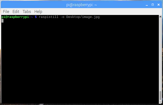
When the command runs, you can see the camera preview open for five seconds before a still picture is taken.
By adding different options, you can set the size and look of the image the raspistill command takes.
-
For example, add
-hand-wto change the height and width of the image:raspistill -o Desktop/image-small.jpg -w 640 -h 480 -
Now record a video with the Camera Module by using the following
raspividcommand:raspivid -o Desktop/video.h264
1.4.6 Working with Camera Using Python Programming Language
-
Taking pictures using Python
from picamera import PiCamera from time import sleep camera = PiCamera() camera.start_preview() sleep(5) camera.stop_preview() -
Recording videos using Python
camera.start_preview()
camera.start_recording('/home/pi/Desktop/video.h264')
sleep(5)
camera.stop_recording()
camera.stop_preview()
1.4.7 Using USK obc command
First install UniSat Software Kit :
sudo pip3 install usk
You can use USK in highly abstracted way, using UniSat’s each board as a top class, and getting it’s value by calling it’s attributes and methods (recommended), for those who want much more detailed information, you can use USK sensors separately.
Example: UniSat Sensorboard as a class (Abstraction)
from usk.Sensor import UniSense # this acts as a whole.

sensor = UniSense()
sensor.update_data()
print(sensor.temperature_bme)
print(sensor.temperature_bno)
print(sensor.pressure)
print(sensor.UVindex)
print(sensor.humidity)
print(sensor.linear_acceleration)
print(sensor.IR)
print(sensor.magnetic)
sensor.print_attrs() # you can get all available attributes by this.
This is helpful when you want to getting started quickly.
import time
from usk.Sensor import UniSense

sensor = UniSense()
sensor.print_attrs()
while True:
    sensor.update_data()
    print(sensor.temperature_bme)
    print(sensor.temperature_bno)
    print(sensor.humidity)
    print(sensor.pressure)
    print(sensor.acceleration)
    print(sensor.gyro)
    print(sensor.magnetic)

    time.sleep(10)
using USK sensors separately
import time
from usk.back import BME
bme = BME()
if bme.ok():
    print(bme.temperature)
    print(bme.pressure)
    print(bme.humidity)
OBC example
from usk.OBC import Pi
pi = Pi()
print(pi.temperature)
print(pi.platform_info)
print(pi.python_version)
print(pi.ram)
print(pi.rom)
Here is the Source code for the OBC command above :
#!/usr/bin/python3
r"""
      __       ___         _______        __        ________        __       ___________
     /""\     |"  |       /"     "|      /""\      /"       )      /""\     ("     _   ")
    /    \    ||  |      (: ______)     /    \    (:   \___/      /    \     )__/  \\__/
   /' /\  \   |:  |       \/    |      /' /\  \    \___  \       /' /\  \       \\_ /
  //  __'  \   \  |___    // ___)     //  __'  \    __/  \\     //  __'  \      |.  |
 /   /  \\  \ ( \_|:  \  (:  (       /   /  \\  \  /" \   :)   /   /  \\  \     \:  |
(___/    \___) \_______)  \__/      (___/    \___)(_______/   (___/    \___)     \__|

                        Created by Azat (@azataiot) on Sep.29 2020
"""
import logging
import os

import click
from click import secho

from obc import settings
from obc.camera import take_picture, take_video
from obc.help import BRANDING
from obc.utils import get_cpu_temperature, get_cpu_usage, get_disk_usage, get_mem_usage, get_core_voltage, show_log_last

# configure logging
writepath = os.path.join(settings.LOGS_ROOT, 'system.txt')
logging.basicConfig(filename=writepath,
                    level=logging.DEBUG,
                    filemode='a' if os.path.exists(writepath) else 'w',
                    format='%(asctime)s - %(process)d - %(levelname)s - %(message)s')


# secho("[OBC] INFO: Try sudo if the program dose not works!", fg='bright_green')
# secho(
#         "[OBC] WARN: THE PROGRAM HAS ACCESS TO SYSTEM KERNEL AND ALL CPU GPIOs!\nNOT PROPER USAGE MAY CAUSE "
#         "UNRECOVERABLE HARDWARE DAMAGE!!! ONLY USE IF YOU KNOW WHAT ARE YOU DOING!",
#         fg='bright_yellow')


@click.group()
@click.version_option(message=BRANDING)
def cli():
    secho("AlfaSat Software Kit -- OBC System (obc) ", fg='blue')


@cli.command()
@click.argument('target')
@click.option(
    "--camera_select",
    '-cs',
    default=0,
    type=click.INT,
    help="Select the camera index for systems that has more that one camera, default 0"
)
@click.option(
    "--duration",
    '-d',
    default=5,
    type=click.INT,
    help="Set the video capturing length for TARGET=VIDEO case. default 5 (second)."
)
def get(target, camera_select, duration):
    """Get information from SYSTEM or CAMERA .\n
    target can be one of: \ntemp, cpu, disk, mem, volt, img, video
    """
    if target == 'temp':
        print(get_cpu_temperature())
    elif target == 'cpu':
        print(get_cpu_usage())
    elif target == 'disk':
        print(get_disk_usage())
    elif target == 'mem':
        print(get_mem_usage())
    elif target == 'volt':
        print(get_core_voltage())
    elif target == 'img':
        if take_picture(camera_num=camera_select) == 0:
            secho(f"Image captured successfully, and saved to the default image directory.", fg='bright_green')
        else:
            secho(f"Capturing image from CAM{camera_select} failed.", fg='red')
            result = show_log_last(which_log_file='camera', how_much_line=2)
            for each in result:
                secho(str(each), fg='red')
    elif target == 'video':
        if take_video(camera_num=camera_select, duration=duration) == 0:
            secho(f"Video for {duration} seconds recorded successfully, and saved to the default video directory.",
                  fg='bright_green')
        else:
            secho(f"Capturing video from CAM{camera_select} failed.", fg='red')
            result = show_log_last(which_log_file='camera', how_much_line=2)
            for each in result:
                secho(str(each), fg='red')


if __name__ == "__main__":
    cli()
1.4.8 OBC Actions
OBC Actions :
- Listening : standby and listen for the messages.
- Parsing : Parsing the message, check the source and larget of the message, set the message flag as CALL or FALL.
- CALL requires further actions to be done (except logging ), espacially messages send to the OBC itself.
- FALL messages that send to other board, OBC dose not have to take any action, but have to record the message in to the ANGIME.AZT file(as a part of the logging process).
- Reaction:
- CALL :
- (ASYNC) SHOOT : capture image and save the image data & write shooting history to the SHOOT.AZT file. (Target: Data/shoot/2020-09-03-11-23-42.png)
- (ASYNC) FRAME : record short videos for VAR seconds & write recording history to the FRAME.AZT file. (Target: Data/frame/2020-09-03-11-23-42.mp4)
- FALL :
- ANGIME all message history (APPEND)
- SHOOT all successful capture history (APPEND)
- FRAME all successful video recording history (APPEND)
- TOUCH each VAR minute sensorboard (and maybe also from other board data) DATA and it’s history (APPEND)
- PROCESS system process history
- LOG system crash and errors.
- CALL :
- QUERY: Ask data from other board.
- RESPOND: SEND required data to the BUS.
- MAMA : SYSTEM LEVEL CRASH. MAY BE UN RECOVERABLE
- CHECK : SYSTEM TEMP, SYSTEM MEM, SYSTEM STORAGE.
2 Sensor Board
As it’s obvious by the name, Sensor board is the part which responsible for reading and writing (or responding) sensor data.
2.1 Sensor Board Hardware Overview
As we have talked the OBC hardware design very in detail, we are not going to repeat the process again for sensor board as they are the same in heart but just different on some of the parts and components.
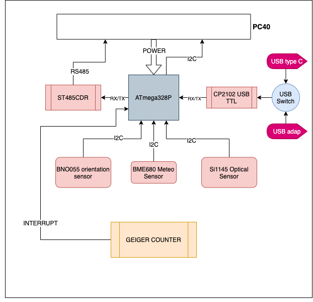
SensorBoard (SB or SBRD below), uses Atmega 328P micro-controller as it’s controller unit, which is the same microcontroller that you can find in an Arduino pro or pro mini 3v3.
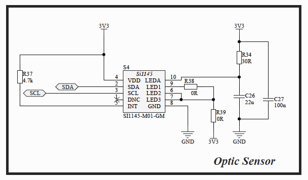
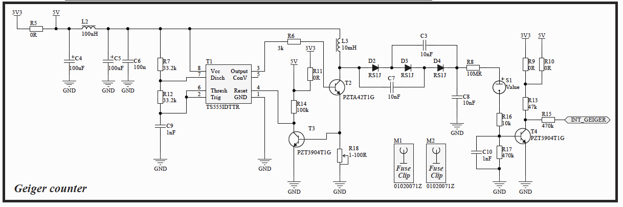
There are several important sensors with various functionality on the sensor board, such as the BNO055 orientation sensor, BME680 Metro Sensor, Si1145 Optical sensor, Geiger counter and etc.
Here in the Table2.1.1, more detailed technical informations about each sensor is given:
| No. | Name of the Component | Sensing Functions | Physical Interface | Part Number |
|---|---|---|---|---|
| 1 | BME680 | Air quality Humidity Temperature Pressure |
I2C | 828-1077-1-ND |
| 2 | BNO055 | Accelerometer Gyroscope Magnetometer |
I2C | 828-1058-1-ND |
| 3 | SI1145 | UV Index IR Visible Light |
I2C | 336-5134-ND |
| 4 | Geiger counter | Geiger Counter | Interrupt | - |
2.2 Sensor Board Hardware Design
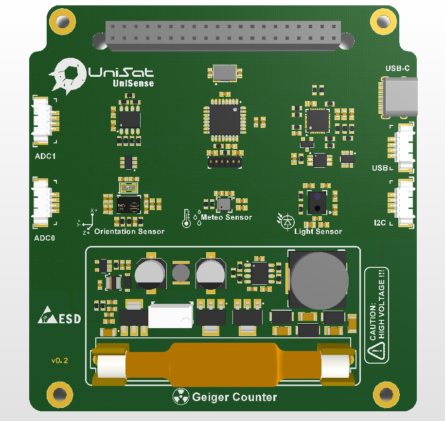
As we can see from the PCB rendering image, Pic2.2.1, the process for designing the PCB is same as designing the PCB for OBC, and here we are not repeating the same process, however, we will focus on some parts that are different from the OBC.
To design the SB hardware, we first learn each of the sensors specifications and circuit design requirements, then place them together Using Altium designer software, as we mentioned before.
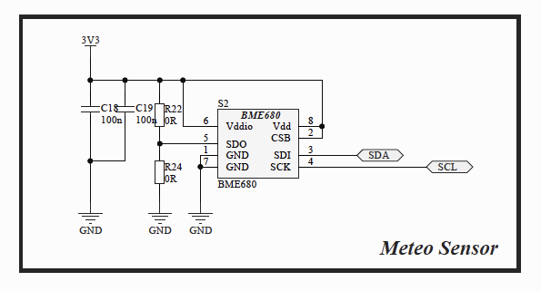
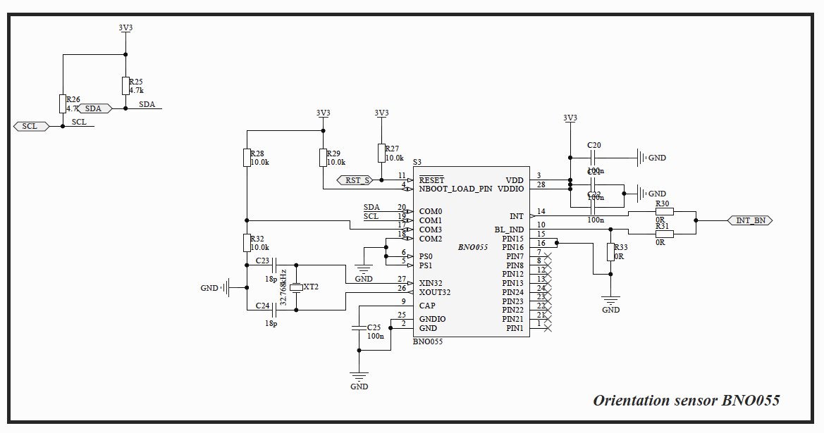
Here below are the circuit information for each of the UniSat SB sensors in Pic2.2.2, Pic2.2.3, Pic2.2.4, Pic2.2.5
2.3 Programming the UniSat Sensor Board
2.3.1 Preparing Development Environment for UniSat SB
Each UniSat Sensorboard has an Atmega 328 Arduino Pro or Pro-mini microcontroller as well as a STM32L0 microcontroller. To develop software for those microcontrollers, we need to set up a programming environment on our PC.
-
Arduino IDE
To develop software for Arduino, Arduino IDE is highly recommended. Arduino IDE is a integrated development environment which take care of all other stuff while you only have to focus on your logic. You can download Arduino IDE from https://arduino.cc , and follow the instructions for installation.
-
Platform IO
Platform IO is a professional collaborative platform for embedded development, which we mainly use to generate and build our Arduino Project. Our Arduino project will be so huge so that we need a proper tool to help us for debugging, analyzing and etc. You can download platform IO from https://platformio.org .
-
GNU Arm Embedded Toolchain
We have installed GNU GCC while we developing software for UniSat OBC, now we need a plugin or extra functionality for GCC to work with embedded devices like STM32. Follow the instructions here for installation : https://developer.arm.com/tools-and-software/open-source-software/developer-tools/gnu-toolchain/gnu-rm
-
STM32CubeIDE
STM32CubeIDE is an Integrated Development Environment for STM32, STM32CubeIDE is an advanced C/C++ development platform with peripheral configuration, code generation, code compilation, and debug features for STM32 microcontrollers and microprocessors. It is based on the Eclipse/CDT framework and GCC toolchain for the development, and GDB for the debugging. It allows the integration of the hundreds of existing plugins that complete the features of the Eclipse IDE. We rely on CubeIDE on developing on STM32. For installation, follow the official installation guide here: https://www.st.com/en/development-tools/stm32cubeide.html
2.3.2 Software Project Structure for UniSat SB
.
├── Core
│   ├── Inc
│   ├── Src
│   └── Startup
├── Drivers
│   ├── CMSIS
│   │   ├── Device
│   │   │   └── ST
│   │   │       └── STM32L0xx
│   │   │           └── Include
│   │   └── Include
│   └── STM32L0xx_HAL_Driver
│       ├── Inc
│       │   └── Legacy
│       └── Src
├── Middlewares
│   └── Third_Party
│       └── FreeRTOS
│           └── Source
│               ├── CMSIS_RTOS
│               ├── include
│               └── portable
│                   ├── GCC
│                   │   └── ARM_CM0
│                   └── MemMang
├── cmake-build-debug
│   ├── CMakeFiles
│   │   ├── 3.17.3
│   │   │   ├── CompilerIdC
│   │   │   └── CompilerIdCXX
│   │   └── SBRD.elf.dir
│   │       ├── Core
│   │       │   ├── Src
│   │       │   └── Startup
│   │       ├── Drivers
│   │       │   └── STM32L0xx_HAL_Driver
│   │       │       └── Src
│   │       └── Middlewares
│   │           └── Third_Party
│   │               └── FreeRTOS
│   │                   └── Source
│   │                       ├── CMSIS_RTOS
│   │                       └── portable
│   │                           ├── GCC
│   │                           │   └── ARM_CM0
│   │                           └── MemMang
│   └── Testing
│       └── Temporary
└── reference
.
├── cmake-build-debug
│   └── CMakeFiles
│       ├── CMakeTmp
│       ├── Debug.dir
│       ├── Production.dir
│       └── Z_DUMMY_TARGET.dir
│           └── src
├── cmake-build-pro8mhzatmega328
│   └── CMakeFiles
│       ├── 3.17.3
│       │   ├── CompilerIdC
│       │   │   └── tmp
│       │   └── CompilerIdCXX
│       │       └── tmp
│       ├── CMakeTmp
│       ├── Debug.dir
│       ├── Production.dir
├── include
├── lib
├── sketch
│   ├── I2C
│   ├── bme680
│   │   └── bme680
│   ├── geiger
│   ├── bno055
│   ├── si1145
│   ├── rs485
│   ├── rawdata
│   └── sbrd
├── src
└── test
Software Structure is one of the most important part for developing the software for the platform, as we have shown above, Graph2.3.1 and Graph 2.3.2 are the Software Structure standards for UniSat Software projects on STM32 and Arduino.
Here we first focus on developing on Arduino, as it is much more easier to start.
After setting up the project structure and initializing the project, we will then need to setup the commands that we are going to receive from the RS485 Bus, as shown below:
// 🛰 CMDs
enum CMD {
    CMD_GET_CMD_LIST = 0x01,
    CMD_STAT = 0x02,
    CMD_GET_ALL = 0x03,
    CMD_GET_BME_ALL = 0x04,
    CMD_GET_BNO_ALL = 0x05,
    CMD_GET_GG_ALL = 0x06,
    CMD_GET_SI_ALL = 0x07,
    CMD_BMET = 0x64,
    CMD_BMEP = 0x65,
    CMD_BMEH = 0x66,
    CMD_BMEG = 0x67,
    CMD_BMEA = 0x68,
    CMD_BNOT = 0x69,
    CMD_BNOA = 0x6A,
    CMD_BNOM = 0x6B,
    CMD_BNOGS = 0x6C,
    CMD_BNOE = 0x6D,
    CMD_BNOL = 0x6E,
    CMD_BNOGR = 0x6F,
    CMD_GGC = 0x78,
    CMD_SIV = 0x82,
    CMD_SIR = 0x83,
    CMD_SUV = 0x84,
    COUNT_CMD = 0x17 // How this is calculated? =(line number of this line - line number of CMD_GET_CMD_LIST)
};
Then we will setup a buffer to store received data:
uint8_t crcForm[2] = {0x00, 0x00};
boolean receiveData = true;
bool sendData = false;
Then we will setup the UniSat Communication Protocol Data frame:
typedef struct {
    uint8_t header[2];
    uint8_t destination;
    uint8_t source;
    uint8_t dataLen;
    uint8_t data[ACP_MAX_BYTES];
    uint8_t crc[2];
    uint8_t total;
} ACP;

ACP acp;
Then we defined our recv function for receiving data from the RS485 Bus:
void recv() {
    byte rb;
    static uint8_t ndx = 0;
    while (rs485.available() > 0 && receiveData) {
        rb = rs485.read();
        acp.data[ndx] = rb;
        ndx++;
        if (ndx >= ACP_MAX_BYTES) {
            ndx = ACP_MAX_BYTES - 1;
        }
    }
    acp.data[ndx] = '\0';
    acp.total = ndx;
    ndx = 0;
    receiveData = false;
    if (acp.total >= 5) {
        // header
        acp.header[0] = acp.data[0];
        acp.header[1] = acp.data[1];
        acp.destination = acp.header[0] >> 4u;
        acp.source = acp.header[0] & 0x0Fu;
        // data len
        acp.dataLen = acp.data[2];
        // data
        // crc
        for (uint8_t i = 0; i <= acp.total; ++i) {
            acp.crc[i] = acp.data[i + 2 + 1 + acp.dataLen];
        }
        // data
        for (uint8_t i = 0; i < acp.dataLen; ++i) {
            acp.data[i] = acp.data[i + 3];
        }
        // total
//        acp.total = 5 + acp.dataLen;

        // crc calculation
        calcCRC();

        // test crc
        if (crcForm[0] == acp.crc[0] && crcForm[1] == acp.crc[1]) {
            receiveData = false;
            switch (acp.data[0]) {
                case CMD_GET_CMD_LIST:
                    actGetCmdList();
                    break;
                case CMD_STAT:
                    actGetStatus();
                    break;
                case CMD_GET_ALL:
                    break;
                case CMD_GET_BME_ALL:
                    actGetBmeAll();
                    break;
                case CMD_GET_BNO_ALL:
                    break;
                case CMD_GET_GG_ALL:
                    actGetGgAll();
                    break;
                case CMD_GET_SI_ALL:
                    actGetSiAll();
                    break;
                case CMD_BMET:
                    actGetBmet();
                    break;
                case CMD_BMEP:
                    actGetBmep();
                    break;
                case CMD_BMEH:
                    actGetBmeh();
                    break;
                case CMD_BMEG:
                    actGetBmeg();
                    break;
                case CMD_BMEA:
                    actGetBmea();
                    break;
                case CMD_BNOT:
                    actGetBnoT();
                    break;
                case CMD_BNOA:
                    actGetBnoA();
                    break;
                case CMD_BNOM:
                    actGetBnoM();
                    break;
                case CMD_BNOGS:
                    actGetBnoGs();
                    break;
                case CMD_BNOE:
                    actGetBnoE();
                    break;
                case CMD_BNOL:
                    actGetBnoL();
                    break;
                case CMD_BNOGR:
                    actGetBnoGr();
                    break;
                case CMD_GGC:
                    actGetGgc();
                    break;
                case CMD_SIV:
                    actGetSiv();
                    break;
                case CMD_SIR:
                    actGetSir();
                    break;
                case CMD_SUV:
                    actGetSuv();
                    break;
                default:
                    receiveData = true;
            }
        }
    }
    receiveData = true;
}
CRC16 is used to make sure that we received a complete and right data, let’s define a function and implement that :
void calcCRC() {
    //
    uint16_t crc = 0xFFFF;
    uint8_t rawLen = acp.dataLen + 3; // header 2 byte + data len 1 byte
    uint8_t rawData[rawLen];
    //rawData start
    rawData[0] = acp.header[0];
    rawData[1] = acp.header[1];
    rawData[2] = acp.dataLen;
    for (uint8_t i = 0; i < rawLen; ++i) {
        rawData[i + 3] = acp.data[i];
    }

    // rawData End
    for (uint8_t pos = 0; pos < rawLen; pos++) {
        crc ^= (uint16_t) rawData[pos];
        for (uint8_t i = 8; i != 0; i--) {
            if ((crc & 0x0001u) != 0) {
                crc >>= 1u;
                crc ^= 0xA001u;
            } else {
                crc >>= 1u;
            }
        }
    }
    crcForm[0] = crc & 0x00ffu;
    crcForm[1] = (crc & 0xff00u) >> 8u;
}
We also need a function to send data to the RS485 Bus, so let’s define a function called send for that:
void send() {
    if (sendData) {
        digitalWrite(5, HIGH); // DE pin high gor sending
        rs485.write((acp.source << 4u) + (acp.destination));
        rs485.write(acp.header[1]);
        rs485.write(acp.dataLen);
        // payload should be given by command handler function
        uint8_t rawLen;
        rawLen = acp.dataLen + 3;
        uint8_t rawData[rawLen];
        rawData[0] = (acp.source << 4u) + (acp.destination);
        rawData[1] = 0x00;
        rawData[2] = acp.dataLen;
        for (uint8_t i = 0; i < acp.dataLen; ++i) {
            rawData[i + 3] = acp.data[i];
            rs485.write(acp.data[i]);
        }
        // crc
        uint16_t crc = 0xFFFF;
        for (uint8_t pos = 0; pos < rawLen; pos++) {
            crc ^= (uint16_t) rawData[pos];
            for (uint8_t i = 8; i != 0; i--) {
                if ((crc & 0x0001u) != 0) {
                    crc >>= 1u;
                    crc ^= 0xA001u;
                } else {
                    crc >>= 1u;
                }
            }
        }
        //
        rs485.write(crc & 0x00ffu);
        rs485.write(((crc & 0xff00u) >> 8u));
        sendData = false;
        digitalWrite(5, LOW);
    }
}
We have implemented our receiving and sending functions as well as our check CRC 16 function, yet the challenging part is coming in the next sections.
2.3.3 Programming the RS485 on UniSat SB
To figure out how RS485/UART communication works on UniSat, we will start from simple examples.
Example 1: Receiving Single Characters
In very many cases all that is needed is to send a single character to the Arduino. Between the upper and lower case letters and the numeric characters there are 62 options. For example you could use ‘F’ for forward, ‘R’ for reverse and ‘S’ for stop.
Code to receive a single character is as simple as this:
#include <Arduino.h>

char receivedChar;
boolean newData = false;
void showNewData();
void recvOneChar();

void setup() {
    Serial.begin(9600);
    Serial.println("Arduino is Ready");
}

void loop() {
    recvOneChar();
    showNewData();
}

void recvOneChar() {
    if (Serial.available() > 0) {
        receivedChar = Serial.read();
        newData = true;
    }
}

void showNewData(){
    if (newData){
        Serial.print("This just in ...");
        Serial.println(receivedChar);
        newData = false;
    }
}
Why code is organized into functions?
Even though this example is short and simple I have deliberately put the code to receive the character into a separate function called recvOneChar() as that makes it simple to add it into any other program. I also have the code for showing the character in the function showNewData() because you can change that to do whatever you want without upsetting the rest of the code.
Example 2: Receiving several characters from the Serial Monitor.
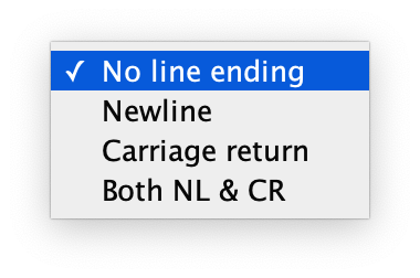
If you need to receive more than a single character from the Serial Monitor (perhaps you want to input people’s names) you will need some method of letting the Arduino know when it has received the full message. The simplest way to do this is to set the line-ending to newline.
This is done with the box at the bottom of the Serial Monitor window. You can choose between “No line ending”, “Newline”, “Carriage return” and “Both NL and CR”. When you select the “Newline” option a new-line character (‘\n’) is added at the end of everything you send.
#include <Arduino.h>

const byte numChars = 32;
char receivedChars[numChars]; // an array to store the received data;
boolean newData = false;

void recvWithMarker();

void showNewData();

void setup() {
    Serial.begin(9600);
    Serial.println("Arduino is Ready");
}

void loop() {
    recvWithMarker();
    showNewData();
}

void recvWithMarker() {
    static byte ndx = 0;
    char endMarker = '\n';
    char rc;

    while (Serial.available() > 0 && !newData) {
        rc = Serial.read();

        if (rc != endMarker) {
            receivedChars[ndx] = rc;
            ndx++;
            if (ndx >= numChars) {
                ndx = numChars - 1;
            }
        } else {
            receivedChars[ndx] = '\0'; // terminate the string
            ndx = 0;
            newData = true;
        }
    }
}

void showNewData() {
    if (newData) {
        Serial.print("This just in ... ");
        Serial.println(receivedChars);
        newData = false;
    }
}
This version of the program reads all the characters into an array until it detects the Newline character as an end marker.
Example 3: A more Complete System
The simple system in Example 2 will work well with a sympathetic human who does not try to mess it up. But if the computer or person sending the data cannot know when the Arduino is ready to receive there is a real risk that the Arduino will not know where the data starts.
If you would like to explore this, change the end marker in the previous program from ‘\n’ to ‘>’ so that you can include the end marker in your text for illustration purposes. (You can’t manually enter a Newline character in the text you are sending from the Serial Monitor). And put the line ending back to “No line ending”
Now, with the revised code send “qwert>” and you will see that it behaves exactly the same as when you were using Newline as the end marker.
But if you try this “asdfg>zxcvb” you will only see the first part “asdfg”. And then if you send “qwert>” you will see “zxcvbqwert” because the Arduino has become confused and cannot know that it should have ignored “zxcvb”.
The answer to this problem is to include a start-marker as well as an end-marker.
#include <Arduino.h>

const byte numChars = 32;
char receivedChars[numChars]; // an array to store the received data;
boolean newData = false;

void recvWithMarker();

void showNewData();

void setup() {
    Serial.begin(9600);
    Serial.println("Arduino is Ready");
}

void loop() {
    recvWithMarker();
    showNewData();
}

void recvWithMarker() {
    static boolean recvInprogress = false;
    static byte ndx = 0;
    char startMarker = '<';
    char endMarker = '>';
    char rc;

    while (Serial.available() > 0 && !newData) {
        rc = Serial.read();
        if (recvInprogress) {
            if (rc != endMarker) {
                receivedChars[ndx] = rc;
                ndx++;
                if (ndx >= numChars) {
                    ndx = numChars - 1;
                }
            } else {
                receivedChars[ndx] = '\0'; // terminate the string
                ndx = 0;
                newData = true;
            }
        } else if (rc == startMarker) {
            recvInprogress = true;
        }
    }
}

void showNewData() {
    if (newData) {
        Serial.print("This just in ... ");
        Serial.println(receivedChars);
        newData = false;
    }
}
To see how it works try sending qwerty<asdfg>zxcvb and you will see that it ignores everything except “asdfg”.
In this program you will notice that there is a new variable called recvInProgress. This is necessary because a distinction needs to be made between unwanted characters that arrive before the start marker and the valid characters that arrive after the start marker.
How it works?
It is important to notice that each time the function recvWithEndMarker() or recvWithStartEndMarker() is called it reads whatever characters may have arrived in the serial input buffer and places them in the array receivedChars.
If there is nothing in the buffer recvWithEndMarker() does not waste time waiting.
In the case of recvWithStartEndMarker() all characters are discarded until the start-marker is detected.
If the end-marker has not yet arrived it will try again when loop() next repeats.
For best results it is important to ensure that loop() can repeat as quickly as possible - hundreds or even thousands of times per second.
How Many Characters Can be Received?
In the examples I have assumed that you will not need to receive more than 32 bytes. That can easily be altered by changing the value in the constant numChars.
Note that the 64 byte size of the Arduino serial input buffer does not limit the number of characters that you can receive because the code in the examples can empty the buffer faster than new data arrives.
Things that are not Used in the Example
You will notice that the examples here do not use any of these Arduino functions
- Serial.parseInt()
- Serial.parseFloat()
- Serial.readBytes()
- Serial.readBytesUntil()
All of these are blocking functions that prevent the Arduino from doing something else until they are satisfied, or until the timeout expires. The examples here do exactly the same job without blocking. That allows the Arduino to do other things while it is waiting for data to arrive.
serialEvent()
I don’t recommend using this function - I prefer to deal with the Serial data when it suits me. It behaves just as if you had this code as the last thing in loop().
if (Serial.available() > 0) {
  mySerialEvent();
}
Clearing the Input Buffer
It is probably worth mentioning that the poorly named Serial.flush() function does not empty the input buffer. It is only relevant when the Arduino is sending data and its purpose is to block the Arduino until all outgoing the data has been sent.
If you need to ensure the Serial input buffer is empty you can do so like this
while (Serial.available() >0 ){
  serial.read();
}
Example4: Receiving a single Number from the Serial Monitor
The simplest case is where you want to type a number into the Serial Monitor (I am assuming you have line-ending set to newline). Let’s assume you want to send the number 234. This is a variation on Example 2 and it will work with any integer value. Note that if you don’t enter a valid number it will show as 0 (zero).
#include <Arduino.h>

const byte numChars = 32;
char receivedChars[numChars]; // an array to store the received data;
boolean newData = false;
int dataNumber = 0;


void recvWithMarker();

void showNewNumber();

void setup() {
    Serial.begin(9600);
    Serial.println("Arduino is Ready");
}

void loop() {
    recvWithMarker();
    showNewNumber();
}

void recvWithMarker() {
    static byte ndx = 0;
    char endMarker = '\n';
    char rc;
    if (Serial.available() > 0) {
        rc = Serial.read();

        if (rc != endMarker) {
            receivedChars[ndx] = rc;
            ndx++;
            if (ndx >= numChars) {
                ndx = numChars - 1;
            }
        } else { // while we have just received a \n
            receivedChars[ndx] = '\0'; // terminate the string
            ndx = 0;
            newData = true;
        }
    }
}

void showNewNumber() {
    if (newData) {
        dataNumber = 0; // new for here
        dataNumber = atoi(receivedChars); // new for here
        Serial.print("This just in ... ");
        Serial.println(receivedChars);
        Serial.print("Data as Number ... ");
        Serial.println(dataNumber);
        newData = false;
    }
}
Example 5: Receiving and Parsing Several Pieces of Data
It is also straightforward to receive several pieces of data in a single message and parse the data to assign them to individual variables. This example assumes you send something like “<HelloWorld, 12, 24.7>”. This is an extension of Example 3.
A function called parseData() has been added and the function showParsedData() takes the place of showNewData() in the earlier example.
#include <Arduino.h>

const byte numChars = 32;
char receivedChars[numChars]; // an array to store the received data;
char tempChars[numChars]; // temporary array for use when parsing

// variables to hold the parsed data
char messageFromPC[numChars] = {0};
int integerFromPC = 0;
float floatFromPC = 0.0;

boolean newData = false;


void recvWithStartEndMarkers();

void parseData();

void showParsedData();

void setup() {
    Serial.begin(9600);
    Serial.println("Arduino is Ready");
    Serial.println("This demo expects 3 pieces of data - text, an integer and a floating point value");
    Serial.println("Enter data in this style : <HelloWorld, 12, 3.14> ");
    Serial.println();
}

void loop() {
    recvWithStartEndMarkers();
    if (newData) {
        strcpy(tempChars, receivedChars);
        parseData();
        showParsedData();
        newData = false;
    }
}

void recvWithStartEndMarkers() {
    static boolean recvInProgress = false;
    static byte ndx = 0;
    char startMarker = '<';
    char endMarker = '>';
    char rc;


    while (Serial.available() > 0 && !newData) {
        rc = Serial.read();

        if (recvInProgress) {
            if (rc != endMarker) {
                receivedChars[ndx] = rc;
                ndx++;
                if (ndx >= numChars) {
                    ndx = numChars - 1;
                }
            } else {
                receivedChars[ndx] = '\0'; //terminate the string
                recvInProgress = false;
                ndx = 0;
                newData = true;
            }
        } else if (rc = startMarker) {
            recvInProgress = true;
        }
    }

}

void parseData() {
    // split the data into its parts
    char *strtoKIndex; // this is used by strtok() as an index
    strtoKIndex = strtok(tempChars, ","); // get the first part - the string
    strcpy(messageFromPC, strtoKIndex); // copy the first part to message from pc
    strtoKIndex = strtok(NULL, ","); // this continues where the previous call left off
    integerFromPC = atoi(strtoKIndex);

    strtoKIndex = strtok(NULL, ","); // this continues where the previous call left off
    floatFromPC = atof(strtoKIndex);
}

void showParsedData(){
    Serial.print("Message ");
    Serial.println(messageFromPC);
    Serial.print("Integer ");
    Serial.println(integerFromPC);
    Serial.print("Float ");
    Serial.println(floatFromPC);
}
Example 6: Program to Receive Binary Data
#include <Arduino.h>

const byte numBytes = 32;
byte receivedBytes[numBytes];
byte numReceived = 0;

boolean newData = false;


void recvBytesWithStartEndMarkers();
void showNewData();
void setup() {
    Serial.begin(9600);
    Serial.println("<Arduino is ready>");
}

void loop() {
    recvBytesWithStartEndMarkers();
    showNewData();
}

void recvBytesWithStartEndMarkers() {
    static boolean recvInProgress = false;
    static byte ndx = 0;
    byte startMarker = 0x3C;
    byte endMarker = 0x3E;
    byte rb;


    while (Serial.available() > 0 && !newData) {
        rb = Serial.read();

        if (recvInProgress) {
            if (rb != endMarker) {
                receivedBytes[ndx] = rb;
                ndx++;
                if (ndx >= numBytes) {
                    ndx = numBytes - 1;
                }
            }
            else {
                receivedBytes[ndx] = '\0'; // terminate the string
                recvInProgress = false;
                numReceived = ndx;  // save the number for use when printing
                ndx = 0;
                newData = true;
            }
        }

        else if (rb == startMarker) {
            recvInProgress = true;
        }
    }
}

void showNewData() {
    if (newData) {
        Serial.print("This just in (HEX values)... ");
        for (byte n = 0; n < numReceived; n++) {
            Serial.print(receivedBytes[n], HEX);
            Serial.print(' ');
        }
        Serial.println();
        newData = false;
    }
}
Example 7: Arduino Read HEX from Serial
serialRead() reads one byte at a time from the serial buffer, so in order to print out the whole sentence at once (it is actually still printing one byte at a time but the pc will receive it not interupted by newLines or other printString inside you loop) you must loop untill there are bytes in the serial buffer and and print right away that byte you just read. After that the loop can continue it’s tasks.
#include "Arduino.h"

int serIn; // var that hold the bytes in read from the serialBuffer.
void setup(){
    Serial.begin(9600);
}

void loop(){
    // simple feedback from Arduino Serial.println("Hello, World!")
    // only if there are bytes in the serial buffer execute the following code
    if (Serial.available()){
        // inform that Arduino heard you saying something
        Serial.print("Arduino heard you say: ");
        // keep reading and printing from serial until there are bytes in the serial buffer
        while (Serial.available()>0){
            serIn = Serial.read(); // read Serial
            Serial.print(serIn, BIN); // prints the character just read
        }
    }
    // the serial buffer is over just go to the line (or pass your favorite stop char)
    Serial.println();
    delay(1000);
}
So far we are able to send and receive binary data to and from the RS485 Communication Bus on UniSat.
2.3.43 Programming the BME680,BNO055,SI1145 on UniSat SB
First we need to define a bme680 struct:
// BME680
typedef struct {
    int32_t temp;
    int32_t humidity;
    int32_t pressure;
    int32_t gas;
    int32_t alt;
} BME;

BME bme;

BME680_Class BME680;  ///< Create an instance of the BME680 class
///< Forward function declaration with default value for sea level
float altitude(const int32_t press, const float seaLevel = 1013.25);

float altitude(const int32_t press, const float seaLevel) {
    static float Altitude;
    Altitude =
            44330.0 * (1.0 - pow(((float) press / 100.0) / seaLevel, 0.1903));  // Convert into meters
    return (Altitude);
}

void updateBmeData(); // update BME680 Data
// BME680 END
Then we will define several functions to handle data:
void actGetBmet() {
    // 0x64
    updateBmeData();
    // temp
    acp.data[0] = bme.temp >> 24;
    acp.data[1] = bme.temp >> 16;
    acp.data[2] = bme.temp >> 8;
    acp.data[3] = bme.temp & 0xff;
    // send
    acp.dataLen = 4;
    sendData = true;
}

void actGetBmep() {
    // 0x65
    updateBmeData();
    // press
    acp.data[0] = bme.pressure >> 24;
    acp.data[1] = bme.pressure >> 16;
    acp.data[2] = bme.pressure >> 8;
    acp.data[3] = bme.pressure & 0xff;
    // send
    acp.dataLen = 4;
    sendData = true;

}

void actGetBmeh() {
    // 0x66
    updateBmeData();
    // humidity
    acp.data[0] = bme.humidity >> 24;
    acp.data[1] = bme.humidity >> 16;
    acp.data[2] = bme.humidity >> 8;
    acp.data[3] = bme.humidity & 0xff;
    // send
    acp.dataLen = 4;
    sendData = true;
}

void actGetBmeg() {
    // 0x67
    updateBmeData();
    // gas
    acp.data[0] = bme.gas >> 24;
    acp.data[1] = bme.gas >> 16;
    acp.data[2] = bme.gas >> 8;
    acp.data[3] = bme.gas & 0xff;
    // send
    acp.dataLen = 4;
    sendData = true;
}

void actGetBmea() {
    //0x68
    // altitude
    acp.data[0] = bme.alt >> 24;
    acp.data[1] = bme.alt >> 16;
    acp.data[2] = bme.alt >> 8;
    acp.data[3] = bme.alt & 0xff;
    // send
    acp.dataLen = 4;
    sendData = true;
}
We also need a function to update and query data from the sensor using I2C:
void updateBmeData() {
    BME680.getSensorData(bme.temp, bme.humidity, bme.pressure, bme.gas);   // Get readings
    bme.alt = (int) (altitude(bme.pressure) * 100);
}
Programming the BNO055 and SI1145 are the same as programming the BME680, as all of them use I2C to communicate.
2.3.7 Programming the Geiger counter on UniSat SB
First let’s define some macros and time delta for the counter:
// Geiger
#include <SPI.h>

#define LOG_PERIOD 15000  //Logging period in milliseconds, recommended value 15000-60000.
#define MAX_PERIOD 60000 //Maximum logging period

uint16_t counts;     //variable for GM Tube events
uint16_t cpm;        //variable for CPM
unsigned int multiplier;  //variable for calculation CPM in this sketch
unsigned long previousMillis;  //variable for time measurement
Then let’s write a function which updates the Geiger data:
void geiger() {
    unsigned long currentMillis = millis();
    if (currentMillis - previousMillis > LOG_PERIOD) {
        previousMillis = currentMillis;
        cpm = counts * multiplier;
        digitalWrite(10, HIGH);
        counts = 0;
    }
}
So far we have finished programming all of the UniSat sensors on Arduino.