
Today We are going to talk about K36/K37, the planet(s) where I came from. You maybe fonfused, why am I talking about the planets on an article of which the title is about something called “Protocol”, I believe you are confusing, yes, that is what humans always do.
The post here assumes that AlfaSat and UniSat is a joint of each, as a single or completly same device except parts of hardware design.
Technichal Terms
AlfaSat
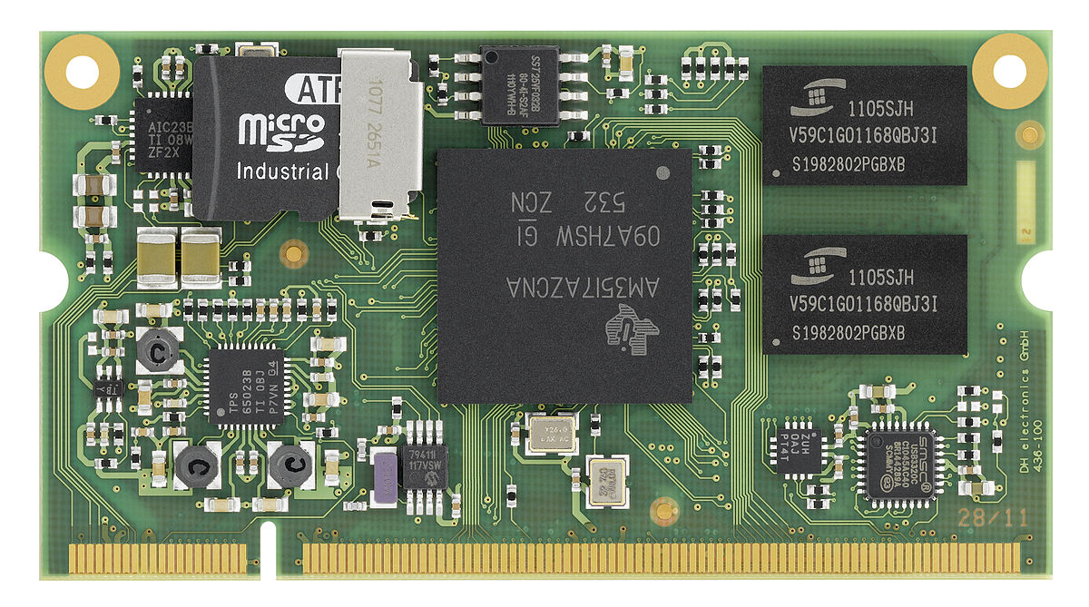
AlfaSat Hardware
AlfaSat (or UniSat) is a nano-satellite which consists from several main hardware parts, including the TOP BOARD, EPS BOARD, OBC BOARD, SENSOR BOARD (AlfaSense), TRX BOARD, ANTENNA BOARD, as shown in the diagram below:
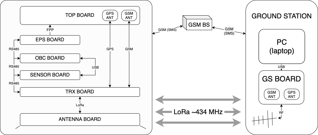
The communication internally and externally with the satellite is estabilished on a common rule, as called, AlfaSat Protocol, Physically that is a RS485 Serial Communication Bus.
This post will not focus on boards except OBC and the Sensorboard, as they are the dominant source for the data, other boards follows the same rule and should work very similarly.
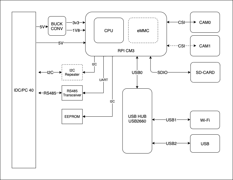
The On Board Computer (OBC)
On board computer (OBC) is the major brain of the satellite, responsible for all core functions, like collecting the system data, logging, error handling, data monitoring, and etc.
Here we have two cameras on OBC, one as a general RPi camera that responsible for capturing beautiful space images while the other is responsible for video recordings.
The capturing task (both imaging and video recording) is a software designed task that runs among almost all the satellite life time in a cycled period.
OBC Actions :
- Listening : standby and listen for the messages.
- Parsing : Parsing the message, check the source and larget of the message, set the message flag as CALL or FALL.
- CALL requires further actions to be done (except logging ), espacially messages send to the OBC itself.
- FALL messages that send to other board, OBC dose not have to take any action, but have to record the message in to the ANGIME.AZT file(as a part of the logging process).
- Reaction:
- CALL :
- (ASYNC) SHOOT : capture image and save the image data & write shooting history to the SHOOT.AZT file. (Target: Data/shoot/2020-09-03-11-23-42.png)
- (ASYNC) FRAME : record short videos for VAR seconds & write recording history to the FRAME.AZT file. (Target: Data/frame/2020-09-03-11-23-42.mp4)
- FALL :
- ANGIME all message history (APPEND)
- SHOOT all successful capture history (APPEND)
- FRAME all successful video recording history (APPEND)
- TOUCH each VAR minute sensorboard (and maybe also from other board data) DATA and it’s history (APPEND)
- PROCESS system process history
- LOG system crash and errors.
- CALL :
- QUERY: Ask data from other board.
- RESPOND: SEND required data to the BUS.
- MAMA : SYSTEM LEVEL CRASH. MAY BE UN RECOVERABLE
- CHECK : SYSTEM TEMP, SYSTEM MEM, SYSTEM STORAGE.
TODO : FURTHER DEFINITIONS AND CONCRETE EXPLANATIONS AND SAMPLE”S REQUIRED>.
The Sensor Board
As it’s obvious by the name, Sensorboard is the part which responsible for reading and writing (or responding) sensor data.
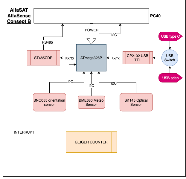
Sensorboard should work properly during the ascending and the decending process.
The Sensorboard Actions:
- Listening : standby and listen for the messages.
- Parsing : Parsing the message, check the source and larget of the message, set the message flag as LOVE or POKE.
- LOVE requires response. And should return some data to the outside. (GET OR SET)
- POKE message is not send for the Sensorboard and can be ignored.
- Reaction:
- GET:
- GET from cache array
- GET from REAL-TIME
- SET : set global variables
- GET:
- RESPOND: SEND required data to the BUS.
The Satellite Life Cycle
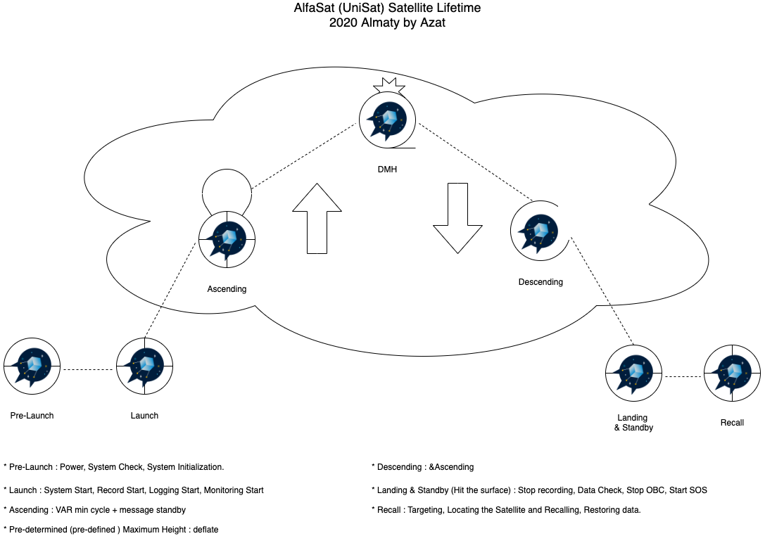
The satellite life cycle is very important for structuring the software code by period and testing. As is mensioned, Sensor Board and OBC has major functions during the life cycle.
Digital Data
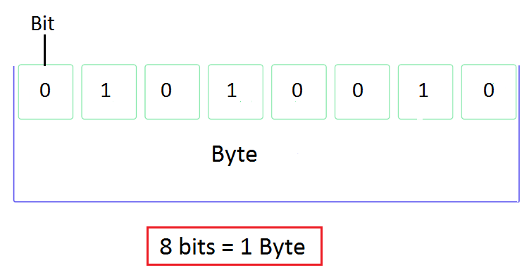
Digital data is a natural choice for communications. The smallest unit of digital data is a Bit, or binary digit, and it has just two states: Off, represented by a 0; and On, represented by a 1. Since the 1960s, most computerized devices have relied on miniaturized, two-state transistors that are either off or on. And a voltage associated with the transistor is either low (0) or high (1). A bit’s value is represented using base 2, and can only be 0 or 1. Digital data can be generated and transmitted very quickly by electronic equipment.
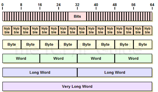
Almost all transmitted data is at least one byte long. A byte consists of 8 consecutive bits, or binary digits. A byte can have up to 256 (28 ) values. In reality, data is frequently communicated in 2, 4 or 8 byte units. A data unit with 2 bytes (16 bits) is often called a Word.
Measurements that mean something in the real world - levels, pressures, temperatures, etc. - can easily be represented with 2 or 4 bytes. So can the ranges of set points. Likewise the On or Off state of a device like a motor. Within computers and microprocessors, arithmetic operations on data that has a digital equivalent is readily done. They can easily manipulate data in binary, or base 2.
Before microprocessor-based controllers became the dominant control technology in the early 1980s, controllers for applications like refineries, chemical plants, and power plants mostly used analog electronic control systems.
Analog signals vary in a range. These analog systems had some serious limitations. One was that analog signals were susceptible to being corrupted by electrical noise and unintentional grounds. Another was that settings and calculated values in control loops tended to drift over time, especially as components heated up.
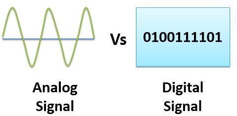
Digital data communications through protocols has the advantages that it is inherently more stable, reliable, and less susceptible to electrical noise than analog signals.
Another advantage of digital communications is that a lot of data can be communicated on a single network or fieldbus cable. This reduces end users’ needs for installing controller input and output modules, wiring, conduit, etc. It also lets users connect different types of devices to the same communications cable, such as transmitters and actuators. And it also makes it easier find the sources of problem conditions readily.
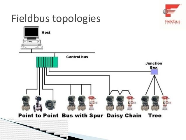
Fieldbus is defined as “a family of industrial computer network protocols used for realtime distributed control, standardized as IEC 61158.”
Worldwide, plants are continuing to use sensors, transmitters and actuators that transmit or respond to analog signals. Controllers handle that by embedding Analog-to-Digital (A/D) and Digital-toAnalog (D/A) converters in input and output modules. For example, most incoming analog signals are converted from a voltage1 to a 16-bit integer within a controller. That makes it easy for a controller to use the data.
Binary
Hexadecimal
ASCII
Network, Nodes, and Topologies
A Network is an interconnected group of computers and/or controllers, and devices that interact with computers and controllers. A Node is a computer or other device in a network. Networks are interconnected by different types of conversion devices, cables, and sometimes, by radio transceivers.
3 common topologies, or arrangements for networks, are discussed below:
- BUS
- STAR
- Ring
graph LR
networks --> Bus & Star & Ring
The Bus topology is the simplest.
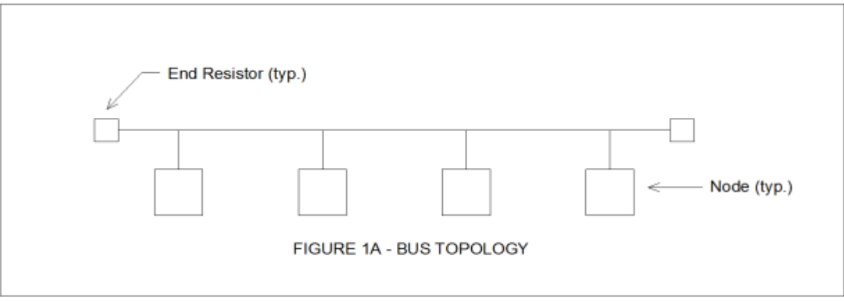
Note the presence of resistors at the ends of the bus. Each node is exposed to data traffic on the bus, but it will only respond if data is directed to it. Otherwise the data is ignored. A bus topology has the disadvantage that failure of the bus cable will stop communications. End resistors with identical resistances are used to improve signal quality on the bus.
AlfaSat (UniSat ) Uses a RS 485 Modbus RTU Network.
A Point-to-Point connection is the simplest example of the bus topology. Point-to-point connections are used, for example, to connect a PC and a single printer.
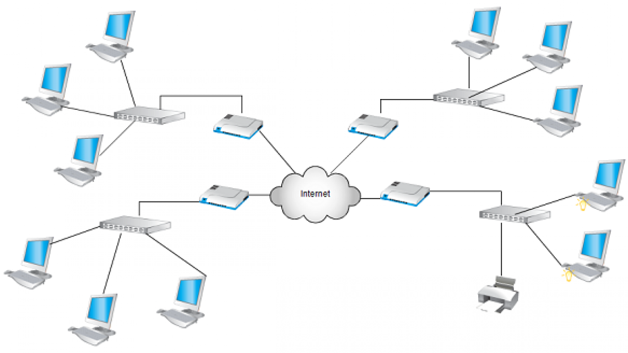
Star topology:

In a Star topology (Figure 1B), individual nodes are connected to a central node. In a Star topology (Figure 1B), individual nodes are connected to a central node. Very often the central node is a Switch. Switches allow temporary pathways to be made so any node on the network can communicate with any other node. In a star topology, an individual node can be disconnected without affecting communications on the rest of the network. It’s more reliable than a bus topology. All data traffic stops if the central node fails. However, switches are built for high reliability, and often, Uninterruptible Power Supplies are connected to provide temporary backup power in event of loss of line power. Sometimes redundant switches are used for improved reliability. In that case, each node has two ports, with separate cables attached to each distributed node.
Ring Topology:
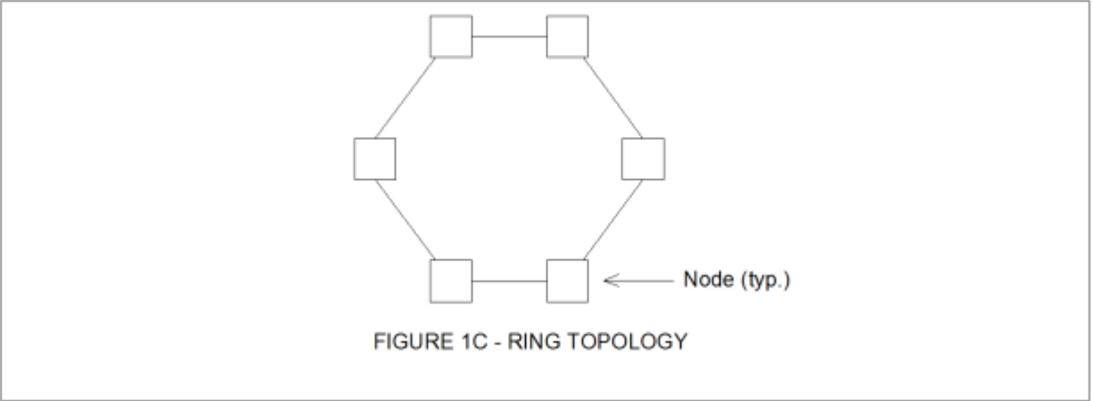
Figure 1C on page 9 illustrates the Ring topology. The ring doesn’t have a master device. Each node can both send and transmit data. Data sent from one node to another is forwarded around the ring from the originating node to the destination node to which it is addressed. If a segment fails, data can be sent in the reverse direction.
Many different types of devices besides computers, controllers and switches can be can be part of a network – such as printers, scanners, barcode readers, TV camera, etc.
In reality, networks are interconnected in many different ways. Some networks consist of combinations of one or more of the three basic networks. In a properly set-up network, data can get from one node to another as long as a path for data transmission exists.
Most networks have a central computer known as a Server. Servers are computers which meet higher standards for dependability, durability, and speed of access to data than ordinary desktop computers. Typically they also have far larger data storage capacity. Servers are frequently set up in redundant pairs. Computers in a network which act only as “dumb terminals” - which operators can use for monitoring and control, but don’t directly interact with controllers or perform processing tasks - are referred to as Clients. A server processes requests from its clients and interacts with controllers. Servers are often referred to as Thick Clients, and client PCs are sometimes called Thin Clients. Such networks are usually called Client-Server Networks.
Many plants and facilities have multiple client PCs and controllers in various locations. So use of servers in process control applications is sensible for 4 reasons: first, to centralize key databases used to monitor the site in one reliable computer (or redundant pair of computers). Second, historical data can be stored on servers. Third, use of servers simplifies access to shared resources such as printers. Last, a Client-Server network allows appropriate delegation of roles and tasks to different entities.
And client operator terminals that are networked with a server can access the server’s database(s) for several purposes:
- To allow operators to monitor operations at a plant’s subsystems.
- To let operators start and stop equipment as needed, and adjust set points for automatic control.
- To view alarm screens
- To access trend screens which show how key levels, pressures, temperatures, etc., have varied over time.
- To view accumulated values such as total flow in a day, and numbers of equipment starts.
- To view archived data.
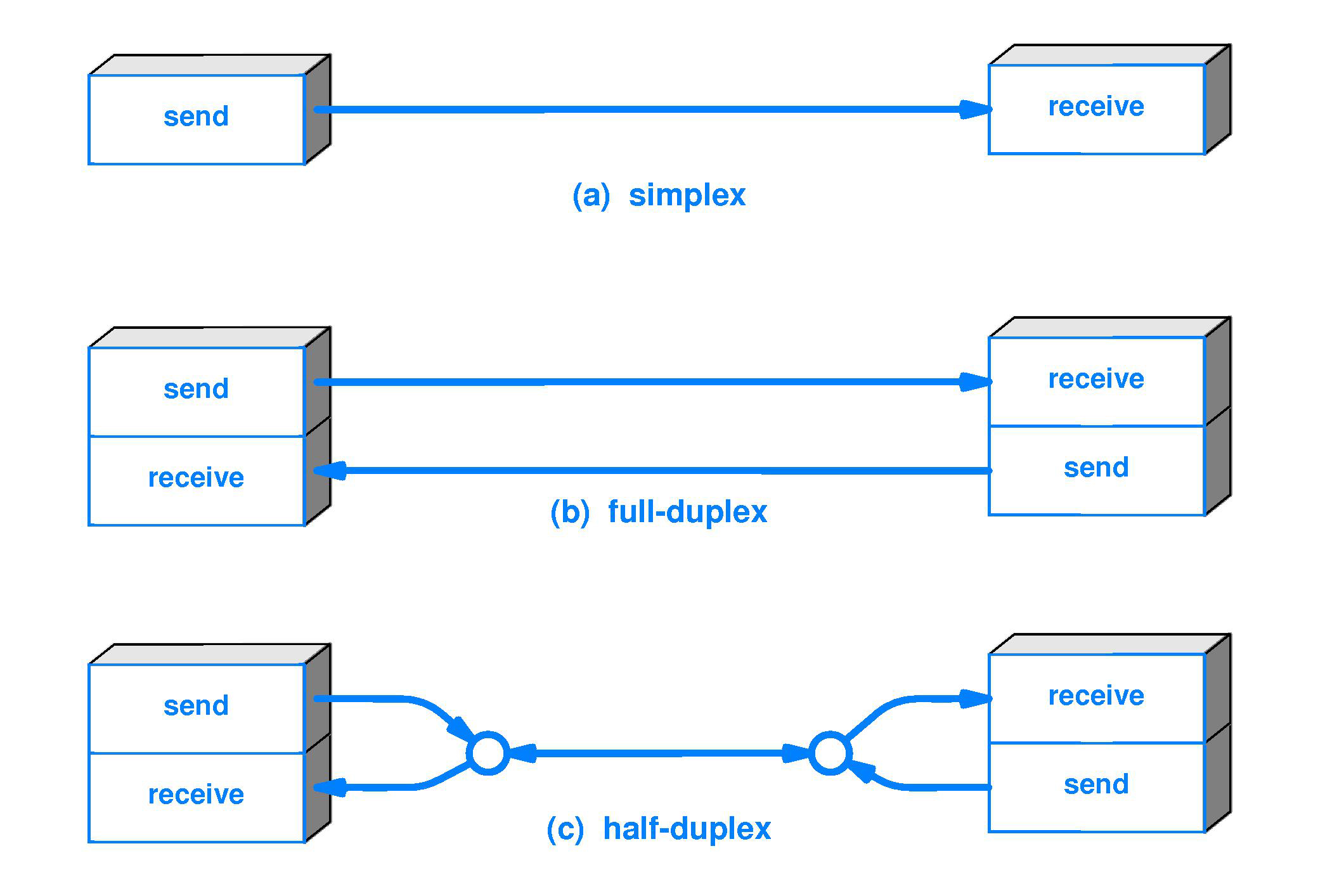
Some communication cables have one group of conductors or fibers for communication in one direction, and another group of conductors or fibers for communication in the other direction.
Regarding such cables, two communications terms sometimes used are Half-duplex and Full-duplex. Half-duplex refers to the transmission of data in only one direction at a time on a cable or other data link. Full-duplex refers to the transmission of data in two directions simultaneously. Typical copper Ethernet cable has separate pairs of conductors for data transfer in opposite directions.
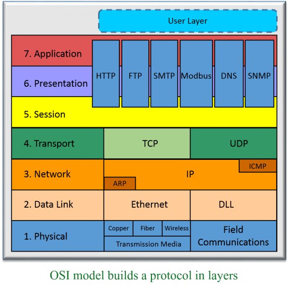
The OSI Model and its importance
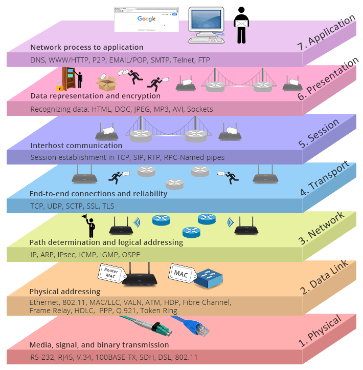
The OSI, or Open Systems Interconnect model, is the next topic. The OSI model is a theoretical model of how communications occur on a network. It has 7 layers. It’s helpful to refer to the OSI model to explain features of protocols, hardware and networks. The layers are:
| 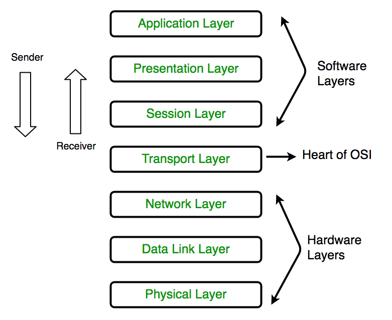 |
- Layer 1 (Physical): This layer considers only the physical aspects of a network; the cables, converters, interconnecting devices, etc.
- Layer 2 (Data-link): This layer concerns itself with how Layers 1 and 3 work together.
- Layer 3 (Network): This layer provides an addressing scheme for routing of data and messages.
- Layer 4 (Transport): This layer makes sure that messages get to their correct destination.
- Layer 5 (Session): This layer handles the actual connections between systems.
- Layer 6 (Presentation): This layer deals with the way different systems represent data.
- Layer 7 (Application): This layer concerns itself chiefly with the software applications used on a computer screen.
|  |
Use of protocols involves both software and hardware, and it’s hard, but sometimes necessary, to differentiate between functions performed by hardware devices, and functions performed by software. So it’s helpful to refer to the OSI model sometimes.
Protocol
A protocol is a standard set of rules that allow electronic devices to communicate with each other. These rules include what type of data may be transmitted, what commands are used to send and receive data, and how data transfers are confirmed.
Three elements of protocol :
graph LR
A["protocol"] -->B & C & D
B["type"]
C["command"]
D["check"]
You can think of a protocol as a spoken language. Each language has its own rules(grammar) and vocabulary. If two people share the same language, they can communicate effectively.
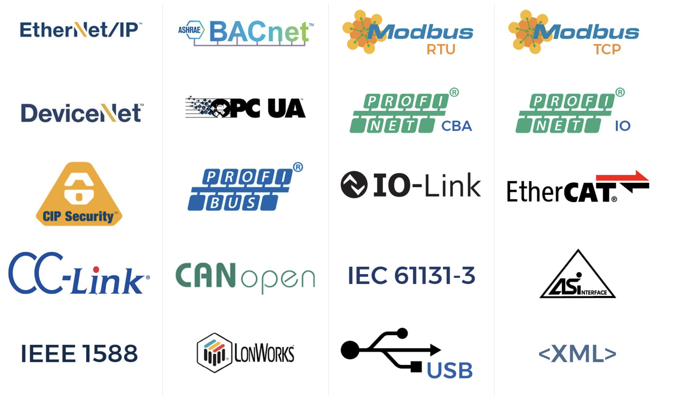
A protocol is a set of rules for communication among networked devices. Some common protocols used in the industrial arena include:
- Modbus RTU
- EtherNet/IP
- Ethernet TCP/IP
- Modbus TCP/IP
- Profinet
Industrial Protocols are vary as below:
Serial & Parallel Communication
Embedded electronics is all about interlinking circuits (processors or other integrated circuits) to create a symbiotic system. In order for those individual circuits to swap their information, they must share a common communication protocol. Hundreds of communication protocols have been defined to achieve this data exchange, and, in general, each can be separated into one of two categories: parallel or serial.
interlink:
Parallel vs. Serial
Parallel interfaces transfer multiple bits at the same time. They usually require buses of data - transmitting across eight, sixteen, or more wires. Data is transferred in huge, crashing waves of 1’s and 0’s.
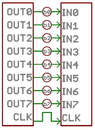
. An 8-bit data bus, controlled by a clock, transmitting a byte every clock pulse. 9 wires are used.
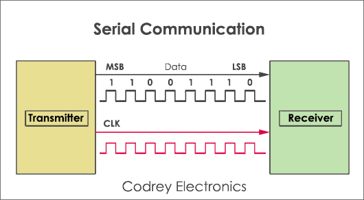
Serial interfaces stream their data, one single bit at a time. These interfaces can operate on as little as one wire, usually never more than four.
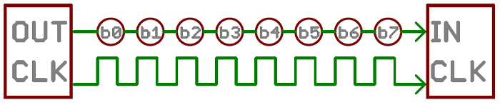
Example of a serial interface, transmitting one bit every clock pulse. Just 2 wires required!
Think of the two interfaces as a stream of cars: a parallel interface would be the 8+ lane mega-highway, while a serial interface is more like a two-lane rural country road. Over a set amount of time, the mega-highway potentially gets more people to their destinations, but that rural two-laner serves its purpose and costs a fraction of the funds to build.
Parallel communication certainly has its benefits. It’s fast, straightforward, and relatively easy to implement. But it requires many more input/output (I/O) lines. If you’ve ever had to move a project from a basic Arduino Uno to a Mega, you know that the I/O lines on a microprocessor can be precious and few. So, we often opt for serial communication, sacrificing potential speed for pin real estate.
Asynchronous Serial
Over the years, dozens of serial protocols have been crafted to meet particular needs of embedded systems. USB (universal serial bus), and Ethernet, are a couple of the more well-known computing serial interfaces. Other very common serial interfaces include SPI, I2C, and others.
Each of these serial interfaces can be sorted into one of two groups: synchronous or asynchronous.
A synchronous serial interface always pairs its data line(s) with a clock signal, so all devices on a synchronous serial bus share a common clock. This makes for a more straightforward, often faster serial transfer, but it also requires at least one extra wire between communicating devices. Examples of synchronous interfaces include SPI, and I2C.
|  |
Asynchronous means that data is transferred without support from an external clock signal. This transmission method is perfect for minimizing the required wires and I/O pins, but it does mean we need to put some extra effort into reliably transferring and receiving data.
e serial protocol we’ll be discussing in this tutorial is the most common form of asynchronous transfers. It is so common, in fact, that when most folks say “serial” they’re talking about this protocol.
Rules of Serial
The asynchronous serial protocol has a number of built-in rules - mechanisms that help ensure robust and error-free data transfers. These mechanisms, which we get for eschewing the external clock signal, are:
- Data bits,
- Synchronization bits,
- Parity bits,
- and Baud rate.
![[webp-to-png output image]](https://raw.githubusercontent.com/azataiot/images/master/2025/02/upgit_20250209_1739105637.png)
Through the variety of these signaling mechanisms, you’ll find that there’s no one way to send data serially. The protocol is highly configurable. The critical part is making sure that both devices on a serial bus are configured to use the exact same protocols.
Baud Rate
The baud rate specifies how fast data is sent over a serial line. It’s usually expressed in units of bits-per-second (bps). If you invert the baud rate, you can find out just how long it takes to transmit a single bit. This value determines how long the transmitter holds a serial line high/low or at what period the receiving device samples its line.
Baud rates can be just about any value within reason. The only requirement is that both devices operate at the same rate. One of the more common baud rates, especially for simple stuff where speed isn’t critical, is 9600 bps. Other “standard” baud are 1200, 2400, 4800, 19200, 38400, 57600, and 115200.
The higher a baud rate goes, the faster data is sent/received, but there are limits to how fast data can be transferred. You usually won’t see speeds exceeding 115200 - that’s fast for most microcontrollers. Get too high, and you’ll begin to see errors on the receiving end, as clocks and sampling periods just can’t keep up.
Framing the Data
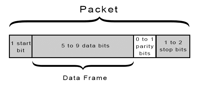
Each block (usually a byte) of data transmitted is actually sent in a packet or frame of bits. Frames are created by appending synchronization and parity bits to our data.
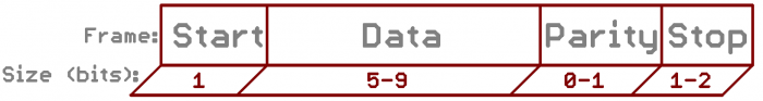
A serial frame. Some symbols in the frame have configurable bit sizes.
Let’s get into the details of each of these frame pieces.
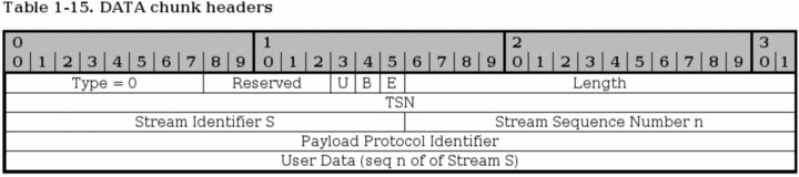
Data chunk
The real meat of every serial packet is the data it carries. We ambiguously call this block of data a chunk, because its size isn’t specifically stated. The amount of data in each packet can be set to anything from 5 to 9 bits. Certainly, the standard data size is your basic 8-bit byte, but other sizes have their uses. A 7-bit data chunk can be more efficient than 8, especially if you’re just transferring 7-bit ASCII characters.
After agreeing on a character-length, both serial devices also have to agree on the endianness of their data. Is data sent most-significant bit (msb) to least, or vice-versa? If it’s not otherwise stated, you can usually assume that data is transferred least-significant bit (lsb) first.
Synchronization bits
The synchronization bits are two or three special bits transferred with each chunk of data. They are the start bit and the stop bit(s). True to their name, these bits mark the beginning and end of a packet. There’s always only one start bit, but the number of stop bits is configurable to either one or two (though it’s commonly left at one).
The start bit is always indicated by an idle data line going from 1 to 0, while the stop bit(s) will transition back to the idle state by holding the line at 1.
Parity bits
Parity is a form of very simple, low-level error checking. It comes in two flavors: odd or even. To produce the parity bit, all 5-9 bits of the data byte are added up, and the evenness of the sum decides whether the bit is set or not. For example, assuming parity is set to even and was being added to a data byte like 0b01011101, which has an odd number of 1’s (5), the parity bit would be set to 1. Conversely, if the parity mode was set to odd, the parity bit would be 0.
Parity is optional, and not very widely used. It can be helpful for transmitting across noisy mediums, but it’ll also slow down your data transfer a bit and requires both sender and receiver to implement error-handling (usually, received data that fails must be re-sent).
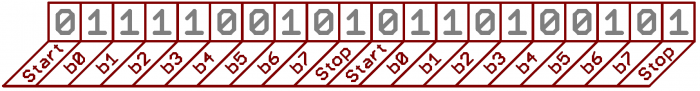
9600 8N1 (an example)
9600 8N1 - 9600 baud, 8 data bits, no parity, and 1 stop bit - is one of the more commonly used serial protocols. So, what would a packet or two of 9600 8N1 data look like? Let’s have an example!
A device transmitting the ASCII characters ‘O’ and ‘K’ would have to create two packets of data. The ASCII value of O (that’s uppercase) is 79, which breaks down into an 8-bit binary value of 01001111, while K’s binary value is 01001011. All that’s left is appending sync bits.
It isn’t specifically stated, but it’s assumed that data is transferred least-significant bit first. Notice how each of the two bytes is sent as it reads from right-to-left.
Since we’re transferring at 9600 bps, the time spent holding each of those bits high or low is 1/(9600 bps) or 104 µs per bit.
For every byte of data transmitted, there are actually 10 bits being sent: a start bit, 8 data bits, and a stop bit. So, at 9600 bps, we’re actually sending 9600 bits per second or 960 (9600/10) bytes per second.
UART
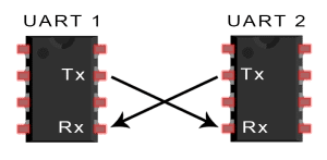
UART stands for Universal Asynchronous Receiver/Transmitter. It’s not a communication protocol like SPI and I2C, but a physical circuit in a microcontroller, or a stand-alone IC. A UART’s main purpose is to transmit and receive serial data.
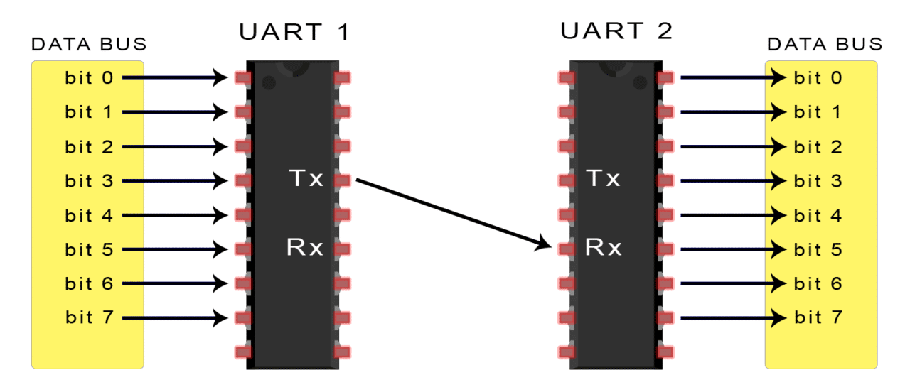
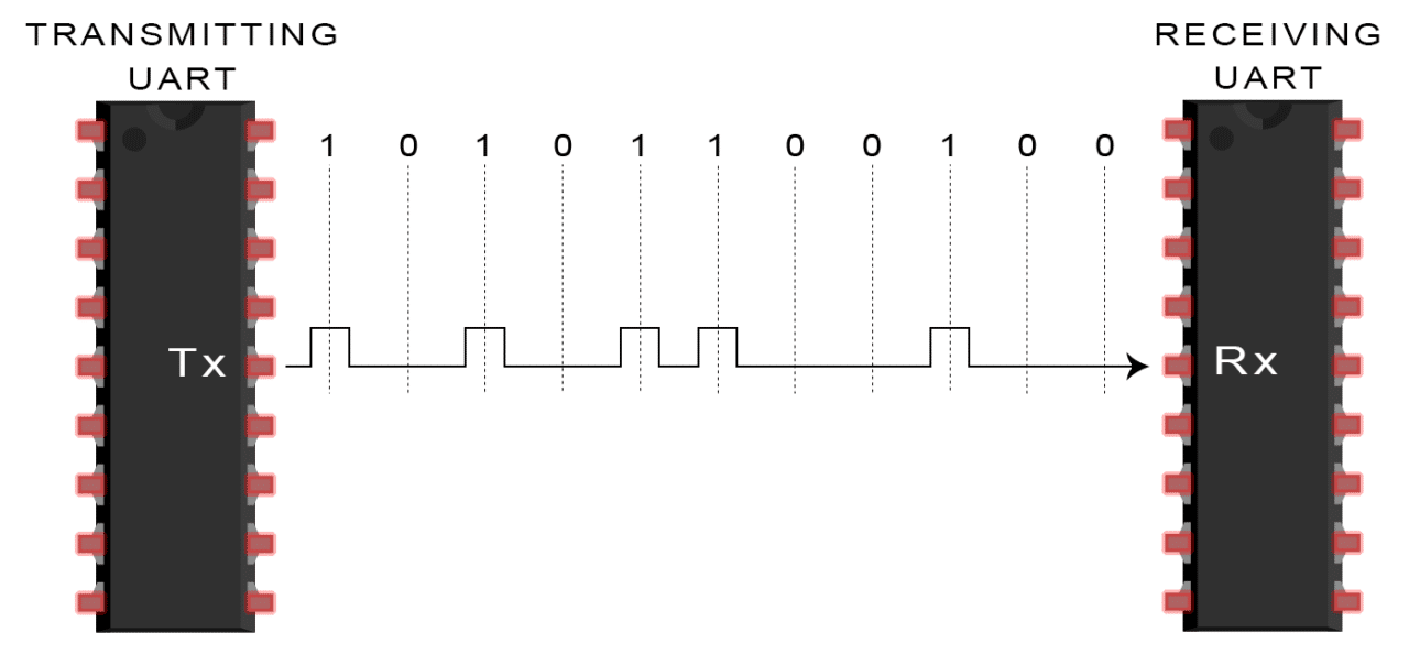
In UART communication, two UARTs communicate directly with each other. The transmitting UART converts parallel data from a controlling device like a CPU into serial form, transmits it in serial to the receiving UART, which then converts the serial data back into parallel data for the receiving device. Only two wires are needed to transmit data between two UARTs. Data flows from the Tx pin of the transmitting UART to the Rx pin of the receiving UART:
UARTs transmit data asynchronously, which means there is no clock signal to synchronize the output of bits from the transmitting UART to the sampling of bits by the receiving UART. Instead of a clock signal, the transmitting UART adds start and stop bits to the data packet being transferred. These bits define the beginning and end of the data packet so the receiving UART knows when to start reading the bits.
When the receiving UART detects a start bit, it starts to read the incoming bits at a specific frequency known as the baud rate. Baud rate is a measure of the speed of data transfer, expressed in bits per second (bps). Both UARTs must operate at about the same baud rate. The baud rate between the transmitting and receiving UARTs can only differ by about 10% before the timing of bits gets too far off.
Both UARTs must also must be configured to transmit and receive the same data packet structure.
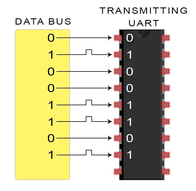
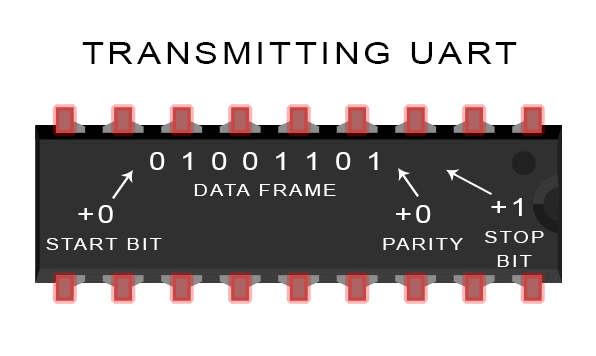
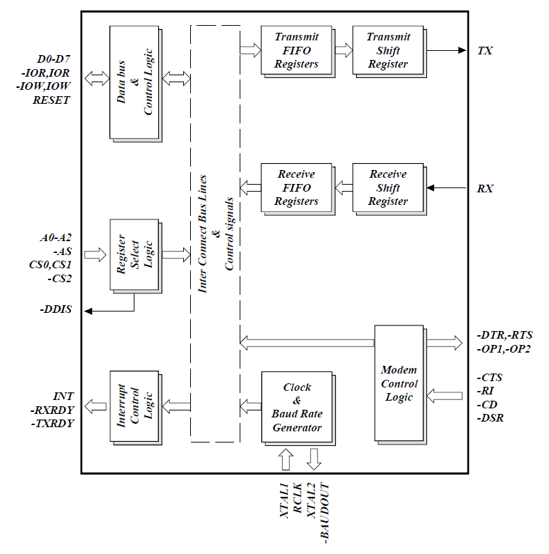
The UART that is going to transmit data receives the data from a data bus. The data bus is used to send data to the UART by another device like a CPU, memory, or microcontroller. Data is transferred from the data bus to the transmitting UART in parallel form. After the transmitting UART gets the parallel data from the data bus, it adds a start bit, a parity bit, and a stop bit, creating the data packet. Next, the data packet is output serially, bit by bit at the Tx pin. The receiving UART reads the data packet bit by bit at its Rx pin. The receiving UART then converts the data back into parallel form and removes the start bit, parity bit, and stop bits. Finally, the receiving UART transfers the data packet in parallel to the data bus on the receiving end:

UART transmitted data is organized into packets. Each packet contains 1 start bit, 5 to 9 data bits (depending on the UART), an optional parity bit, and 1 or 2 stop bits:
Steps of UART TRANSMISSION
-
The transmitting UART receives data in parallel from the data bus:
-
The transmitting UART adds the start bit, parity bit, and the stop bit(s) to the data frame:
-
The entire packet is sent serially from the transmitting UART to the receiving UART. The receiving UART samples the data line at the pre-configured baud rate:
-
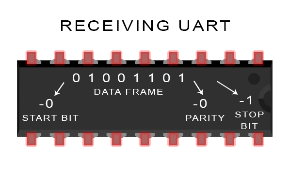
The receiving UART discards the start bit, parity bit, and stop bit from the data frame:
-
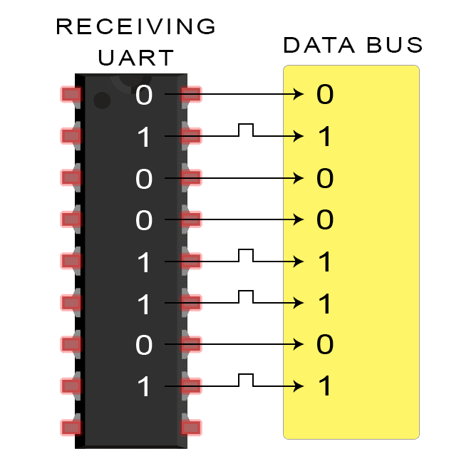
The receiving UART converts the serial data back into parallel and transfers it to the data bus on the receiving end:
Wiring and Hardware
A serial bus consists of just two wires - one for sending data and another for receiving. As such, serial devices should have two serial pins: the receiver, RX, and the transmitter, TX.
It’s important to note that those RX and TX labels are with respect to the device itself. So the RX from one device should go to the TX of the other, and vice-versa. It’s weird if you’re used to hooking up VCC to VCC, GND to GND, MOSI to MOSI, etc., but it makes sense if you think about it. The transmitter should be talking to the receiver, not to another transmitter.
A serial interface where both devices may send and receive data is either full-duplex or half-duplex. Full-duplex means both devices can send and receive simultaneously. Half-duplex communication means serial devices must take turns sending and receiving.
But how is serial communication actually implemented at a signal level? In a variety of ways, actually. There are all sorts of standards for serial signaling. Let’s look at a couple of the more popular hardware implementations of serial: logic-level (TTL) and RS-232.
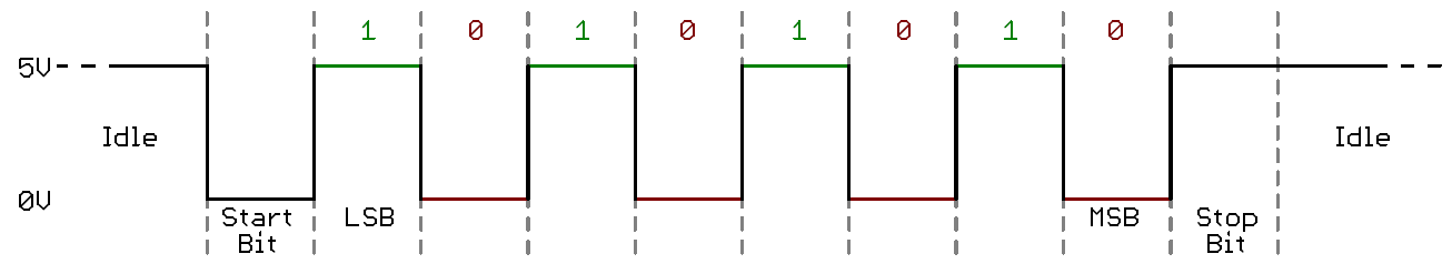
When microcontrollers and other low-level ICs communicate serially they usually do so at a TTL (transistor-transistor logic) level. TTL serial signals exist between a microcontroller’s voltage supply range - usually 0V to 3.3V or 5V. A signal at the VCC level (3.3V, 5V, etc.) indicates either an idle line, a bit of value 1, or a stop bit. A 0V (GND) signal represents either a start bit or a data bit of value 0.
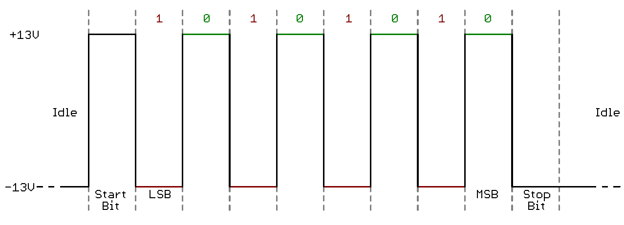
RS-232, which can be found on some of the more ancient computers and peripherals, is like TTL serial flipped on its head. RS-232 signals usually range between -13V and 13V, though the spec allows for anything from +/- 3V to +/- 25V. On these signals a low voltage (-5V, -13V, etc.) indicates either the idle line, a stop bit, or a data bit of value 1. A high RS-232 signal means either a start bit, or a 0-value data bit. That’s kind of the opposite of TTL serial.
Between the two serial signal standards, TTL is much easier to implement into embedded circuits. However the low voltage levels are more susceptible to losses across long transmission lines. RS-232, or more complex standards like RS-485, are better suited to long range serial transmissions.
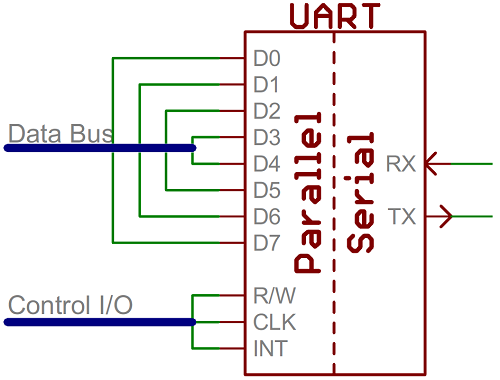
Essentially, the UART acts as an intermediary between parallel and serial interfaces. On one end of the UART is a bus of eight-or-so data lines (plus some control pins), on the other is the two serial wires - RX and TX.
UARTs do exist as stand-alone ICs, but they’re more commonly found inside microcontrollers. You’ll have to check your microcontroller’s datasheet to see if it has any UARTs. Some have none, some have one, some have many. For example, the Arduino Uno - based on the “old faithful” ATmega328 - has just a single UART, while the Arduino Mega - built on an ATmega2560 - has a whopping four UARTs.
As the R and T in the acronym dictate, UARTs are responsible for both sending and receiving serial data. On the transmit side, a UART must create the data packet - appending sync and parity bits - and send that packet out the TX line with precise timing (according to the set baud rate). On the receive end, the UART has to sample the RX line at rates according to the expected baud rate, pick out the sync bits, and spit out the data.
More advanced UARTs may throw their received data into a buffer, where it can stay until the microcontroller comes to get it. UARTs will usually release their buffered data on a first-in-first-out (FIFO) basis. Buffers can be as small as a few bits, or as large as thousands of bytes.
Software UARTs
This is what we use mainly on the AlfaSat.
If a microcontroller doesn’t have a UART (or doesn’t have enough), the serial interface can be bit-banged - directly controlled by the processor. This is the approach Arduino libraries like SoftwareSerial take. Bit-banging is processor-intensive, and not usually as precise as a UART, but it works in a pinch!
RS 485
Modbus
Arduino Logic
Arduino Serial Input Basics
Introduction
Almost all serial input data can be covered by three simple situations:
-
A - when only a single character is required
-
B - when only simple manual input from the Serial Monitor is required
-
C - other
Serial Data is slow by Arduino Standards
When anything sends serial data to the Arduino it arrives into the Arduino input buffer at a speed set by the baud rate.
At 9600 baud about 960 characters arrive per second which means there is a gap of just over 1 millisecond between characters.
The Arduino can do a lot in 1 millisecond so the code that follows is designed not to waste time waiting when there is nothing in the input buffer even if all of the data has not yet arrived. Even at 115200 baud there is still 86 microseconds or 1376 Arduino instructions between characters.
And because data arrives relatively slowly it is easy for the Arduino to empty the serial input buffer even though all of the data has not yet arrived. Many make the mistake of assuming that something like while (Serial.available() > 0) { will pick up all the data that is sent. But it is far more likely that the WHILE will empty the buffer even though only part of the data has arrived.
Example 1: Receiving Single Characters
In very many cases all that is needed is to send a single character to the Arduino. Between the upper and lower case letters and the numeric characters there are 62 options. For example you could use ‘F’ for forward, ‘R’ for reverse and ‘S’ for stop.
Code to receive a single character is as simple as this:
#include <Arduino.h>
char receivedChar;
boolean newData = false;
void showNewData();
void recvOneChar();
void setup() {
Serial.begin(9600);
Serial.println("Arduino is Ready");
}
void loop() {
recvOneChar();
showNewData();
}
void recvOneChar() {
if (Serial.available() > 0) {
receivedChar = Serial.read();
newData = true;
}
}
void showNewData(){
if (newData){
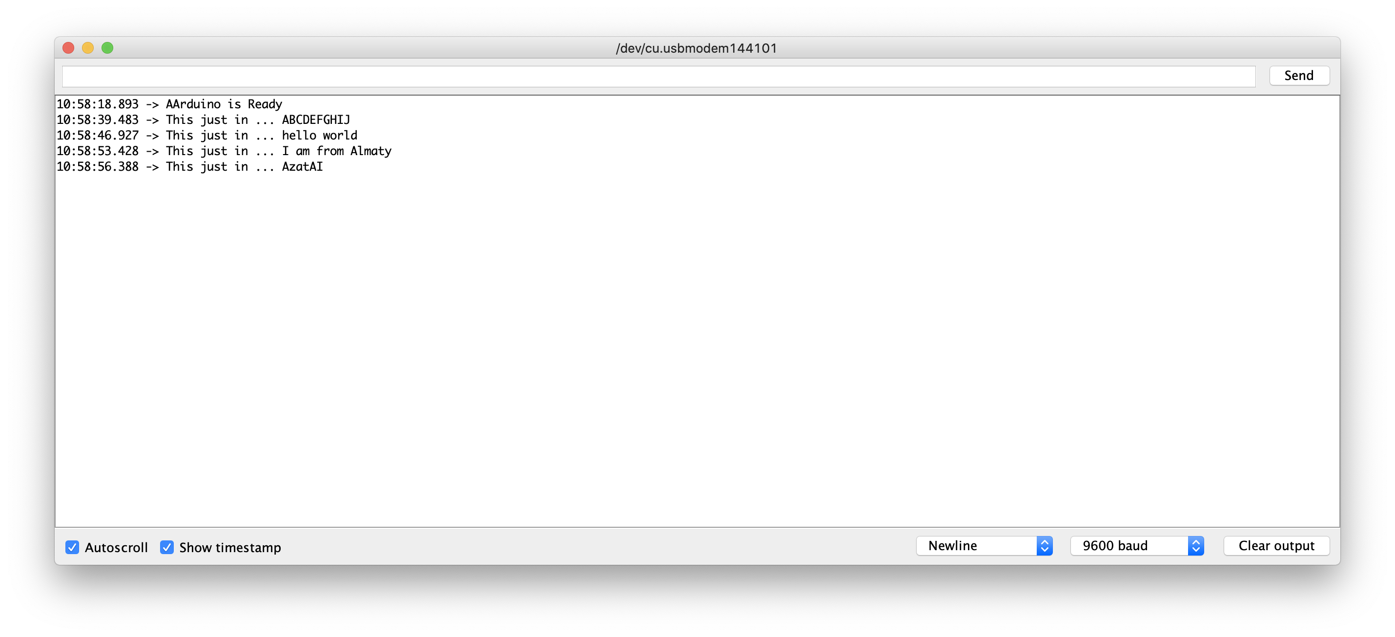
Serial.print("This just in ...");
Serial.println(receivedChar);
newData = false;
}
}
Why code is organized into functions?
Even though this example is short and simple I have deliberately put the code to receive the character into a separate function called recvOneChar() as that makes it simple to add it into any other program. I also have the code for showing the character in the function showNewData() because you can change that to do whatever you want without upsetting the rest of the code.
Example 2: Receiving several characters from the Serial Monitor.
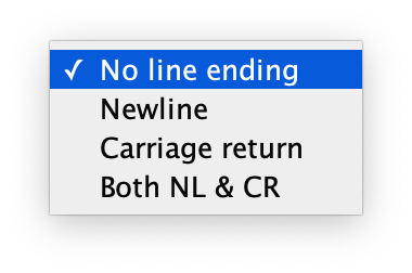
If you need to receive more than a single character from the Serial Monitor (perhaps you want to input people’s names) you will need some method of letting the Arduino know when it has received the full message. The simplest way to do this is to set the line-ending to newline.
This is done with the box at the bottom of the Serial Monitor window. You can choose between “No line ending”, “Newline”, “Carriage return” and “Both NL and CR”. When you select the “Newline” option a new-line character (‘\n’) is added at the end of everything you send.
#include <Arduino.h>

const byte numChars = 32;
char receivedChars[numChars]; // an array to store the received data;
boolean newData = false;

void recvWithMarker();

void showNewData();

void setup() {
    Serial.begin(9600);
    Serial.println("Arduino is Ready");
}

void loop() {
    recvWithMarker();
    showNewData();
}

void recvWithMarker() {
    static byte ndx = 0;
    char endMarker = '\n';
    char rc;

    while (Serial.available() > 0 && !newData) {
        rc = Serial.read();

        if (rc != endMarker) {
            receivedChars[ndx] = rc;
            ndx++;
            if (ndx >= numChars) {
                ndx = numChars - 1;
            }
        } else {
            receivedChars[ndx] = '\0'; // terminate the string
            ndx = 0;
            newData = true;
        }
    }
}

void showNewData() {
    if (newData) {
        Serial.print("This just in ... ");
        Serial.println(receivedChars);
        newData = false;
    }
}
This version of the program reads all the characters into an array until it detects the Newline character as an end marker.
Example 3: A more Complete System
The simple system in Example 2 will work well with a sympathetic human who does not try to mess it up. But if the computer or person sending the data cannot know when the Arduino is ready to receive there is a real risk that the Arduino will not know where the data starts.
If you would like to explore this, change the end marker in the previous program from ‘\n’ to ‘>’ so that you can include the end marker in your text for illustration purposes. (You can’t manually enter a Newline character in the text you are sending from the Serial Monitor). And put the line ending back to “No line ending”
Now, with the revised code send “qwert>” and you will see that it behaves exactly the same as when you were using Newline as the end marker.
But if you try this “asdfg>zxcvb” you will only see the first part “asdfg”. And then if you send “qwert>” you will see “zxcvbqwert” because the Arduino has become confused and cannot know that it should have ignored “zxcvb”.
The answer to this problem is to include a start-marker as well as an end-marker.
#include <Arduino.h>

const byte numChars = 32;
char receivedChars[numChars]; // an array to store the received data;
boolean newData = false;

void recvWithMarker();

void showNewData();

void setup() {
    Serial.begin(9600);
    Serial.println("Arduino is Ready");
}

void loop() {
    recvWithMarker();
    showNewData();
}

void recvWithMarker() {
    static boolean recvInprogress = false;
    static byte ndx = 0;
    char startMarker = '<';
    char endMarker = '>';
    char rc;

    while (Serial.available() > 0 && !newData) {
        rc = Serial.read();
        if (recvInprogress) {
            if (rc != endMarker) {
                receivedChars[ndx] = rc;
                ndx++;
                if (ndx >= numChars) {
                    ndx = numChars - 1;
                }
            } else {
                receivedChars[ndx] = '\0'; // terminate the string
                ndx = 0;
                newData = true;
            }
        } else if (rc == startMarker) {
            recvInprogress = true;
        }
    }
}

void showNewData() {
    if (newData) {
        Serial.print("This just in ... ");
        Serial.println(receivedChars);
        newData = false;
    }
}
To see how it works try sending qwerty<asdfg>zxcvb and you will see that it ignores everything except “asdfg”.
In this program you will notice that there is a new variable called recvInProgress. This is necessary because a distinction needs to be made between unwanted characters that arrive before the start marker and the valid characters that arrive after the start marker.
How it works?
It is important to notice that each time the function recvWithEndMarker() or recvWithStartEndMarker() is called it reads whatever characters may have arrived in the serial input buffer and places them in the array receivedChars.
If there is nothing in the buffer recvWithEndMarker() does not waste time waiting.
In the case of recvWithStartEndMarker() all characters are discarded until the start-marker is detected.
If the end-marker has not yet arrived it will try again when loop() next repeats.
For best results it is important to ensure that loop() can repeat as quickly as possible - hundreds or even thousands of times per second.
How Many Characters Can be Received?
In the examples I have assumed that you will not need to receive more than 32 bytes. That can easily be altered by changing the value in the constant numChars.
Note that the 64 byte size of the Arduino serial input buffer does not limit the number of characters that you can receive because the code in the examples can empty the buffer faster than new data arrives.
Things that are not Used in the Example
You will notice that the examples here do not use any of these Arduino functions
- Serial.parseInt()
- Serial.parseFloat()
- Serial.readBytes()
- Serial.readBytesUntil()
All of these are blocking functions that prevent the Arduino from doing something else until they are satisfied, or until the timeout expires. The examples here do exactly the same job without blocking. That allows the Arduino to do other things while it is waiting for data to arrive.
serialEvent()
I don’t recommend using this function - I prefer to deal with the Serial data when it suits me. It behaves just as if you had this code as the last thing in loop().
if (Serial.available() > 0) {
  mySerialEvent();
}
Clearing the Input Buffer
It is probably worth mentioning that the poorly named Serial.flush() function does not empty the input buffer. It is only relevant when the Arduino is sending data and its purpose is to block the Arduino until all outgoing the data has been sent.
If you need to ensure the Serial input buffer is empty you can do so like this
while (Serial.available() >0 ){
  serial.read();
}
Receiving Numbers Rather Than Text
So far the examples have assumed you want to receive text. But perhaps you want to send a number or maybe a mix of text and numbers.
Example4: Receiving a single Number from the Serial Monitor
The simplest case is where you want to type a number into the Serial Monitor (I am assuming you have line-ending set to newline). Let’s assume you want to send the number 234. This is a variation on Example 2 and it will work with any integer value. Note that if you don’t enter a valid number it will show as 0 (zero).
#include <Arduino.h>

const byte numChars = 32;
char receivedChars[numChars]; // an array to store the received data;
boolean newData = false;
int dataNumber = 0;


void recvWithMarker();

void showNewNumber();

void setup() {
    Serial.begin(9600);
    Serial.println("Arduino is Ready");
}

void loop() {
    recvWithMarker();
    showNewNumber();
}

void recvWithMarker() {
    static byte ndx = 0;
    char endMarker = '\n';
    char rc;
    if (Serial.available() > 0) {
        rc = Serial.read();

        if (rc != endMarker) {
            receivedChars[ndx] = rc;
            ndx++;
            if (ndx >= numChars) {
                ndx = numChars - 1;
            }
        } else { // while we have just received a \n
            receivedChars[ndx] = '\0'; // terminate the string
            ndx = 0;
            newData = true;
        }
    }
}

void showNewNumber() {
    if (newData) {
        dataNumber = 0; // new for here
        dataNumber = atoi(receivedChars); // new for here
        Serial.print("This just in ... ");
        Serial.println(receivedChars);
        Serial.print("Data as Number ... ");
        Serial.println(dataNumber);
        newData = false;
    }
}
if the number is too long, it may exced the integer value range
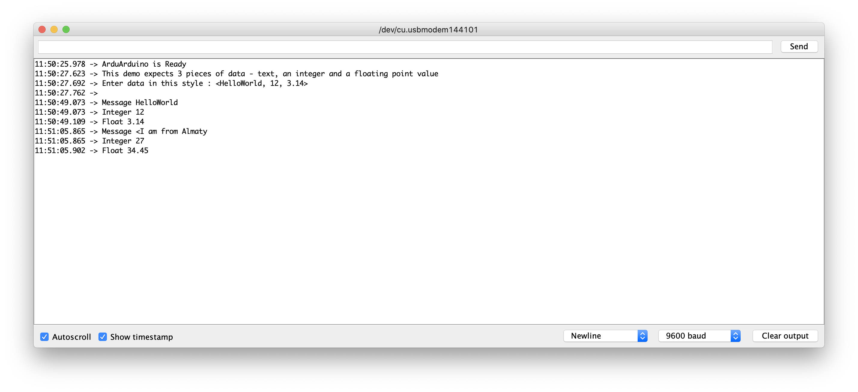
Example 5: Receiving and Parsing Several Pieces of Data
It is also straightforward to receive several pieces of data in a single message and parse the data to assign them to individual variables. This example assumes you send something like “<HelloWorld, 12, 24.7>”. This is an extension of Example 3.
A function called parseData() has been added and the function showParsedData() takes the place of showNewData() in the earlier example.
#include <Arduino.h>

const byte numChars = 32;
char receivedChars[numChars]; // an array to store the received data;
char tempChars[numChars]; // temporary array for use when parsing

// variables to hold the parsed data
char messageFromPC[numChars] = {0};
int integerFromPC = 0;
float floatFromPC = 0.0;

boolean newData = false;


void recvWithStartEndMarkers();

void parseData();

void showParsedData();

void setup() {
    Serial.begin(9600);
    Serial.println("Arduino is Ready");
    Serial.println("This demo expects 3 pieces of data - text, an integer and a floating point value");
    Serial.println("Enter data in this style : <HelloWorld, 12, 3.14> ");
    Serial.println();
}

void loop() {
    recvWithStartEndMarkers();
    if (newData) {
        strcpy(tempChars, receivedChars);
        // this temporary copy is necessary to protect the original data
        // because strtok() used in parseData() replaces the commmas with \0
        parseData();
        showParsedData();
        newData = false;
    }
}

void recvWithStartEndMarkers() {
    static boolean recvInProgress = false;
    static byte ndx = 0;
    char startMarker = '<';
    char endMarker = '>';
    char rc;


    while (Serial.available() > 0 && !newData) {
        rc = Serial.read();

        if (recvInProgress) {
            if (rc != endMarker) {
                receivedChars[ndx] = rc;
                ndx++;
                if (ndx >= numChars) {
                    ndx = numChars - 1;
                }
            } else {
                receivedChars[ndx] = '\0'; //terminate the string
                recvInProgress = false;
                ndx = 0;
                newData = true;
            }
        } else if (rc = startMarker) {
            recvInProgress = true;
        }
    }

}

void parseData() {
    // split the data into its parts
    char *strtoKIndex; // this is used by strtok() as an index
    strtoKIndex = strtok(tempChars, ","); // get the first part - the string
    /*
     * char *strtok(char *s, const char *delim)
     strtok parses the string s into tokens.
     The first call to strtok should have s as its first argument.
     Subsequent calls should have the first argument set to NULL.
     If a token ends with a delimiter, this delimiting character is overwritten with a '\\0'
     and a pointer to the next character is saved for the next call to strtok.
     The delimiter string delim may be different for each call.
     */
    strcpy(messageFromPC, strtoKIndex); // copy the first part to message from pc
    strtoKIndex = strtok(NULL, ","); // this continues where the previous call left off
    integerFromPC = atoi(strtoKIndex);

    strtoKIndex = strtok(NULL, ","); // this continues where the previous call left off
    floatFromPC = atof(strtoKIndex);
}

void showParsedData(){
    Serial.print("Message ");
    Serial.println(messageFromPC);
    Serial.print("Integer ");
    Serial.println(integerFromPC);
    Serial.print("Float ");
    Serial.println(floatFromPC);
}
Binary Data
So far we have been receiving character data - for example the number 121 is represented by the characters ‘1’, ‘2’ and ‘1’. It is also possible to send that value as binary data in a single byte - it happens to be the Ascii value for the character ‘y’. Note that 121 in decimal is the same as 0x79 in HEX
Note that if you are sending binary data it is quite likely that you will need to send as data the same values that are used for the start- and end-markers.
The examples that follow assume that the binary data will NEVER include the byte values used for the start- and end-markers.
The examples that follow assume that the binary data will NEVER include the byte values used for the start- and end-markers. For simplicity I will continue to use < and > as the markers. The byte values for those characters are 0x3C and 0x3E. This will allow you to test the program from the Serial Monitor by sending, for example, <24y> which will be interpreted by the receiving program as the binary values 0x32, 0x34 and 0x79. These are the Ascii codes for 2, 4 and y.
Of course it would be more usual for binary data to be sent by another computer program - on another Arduino or on a PC.
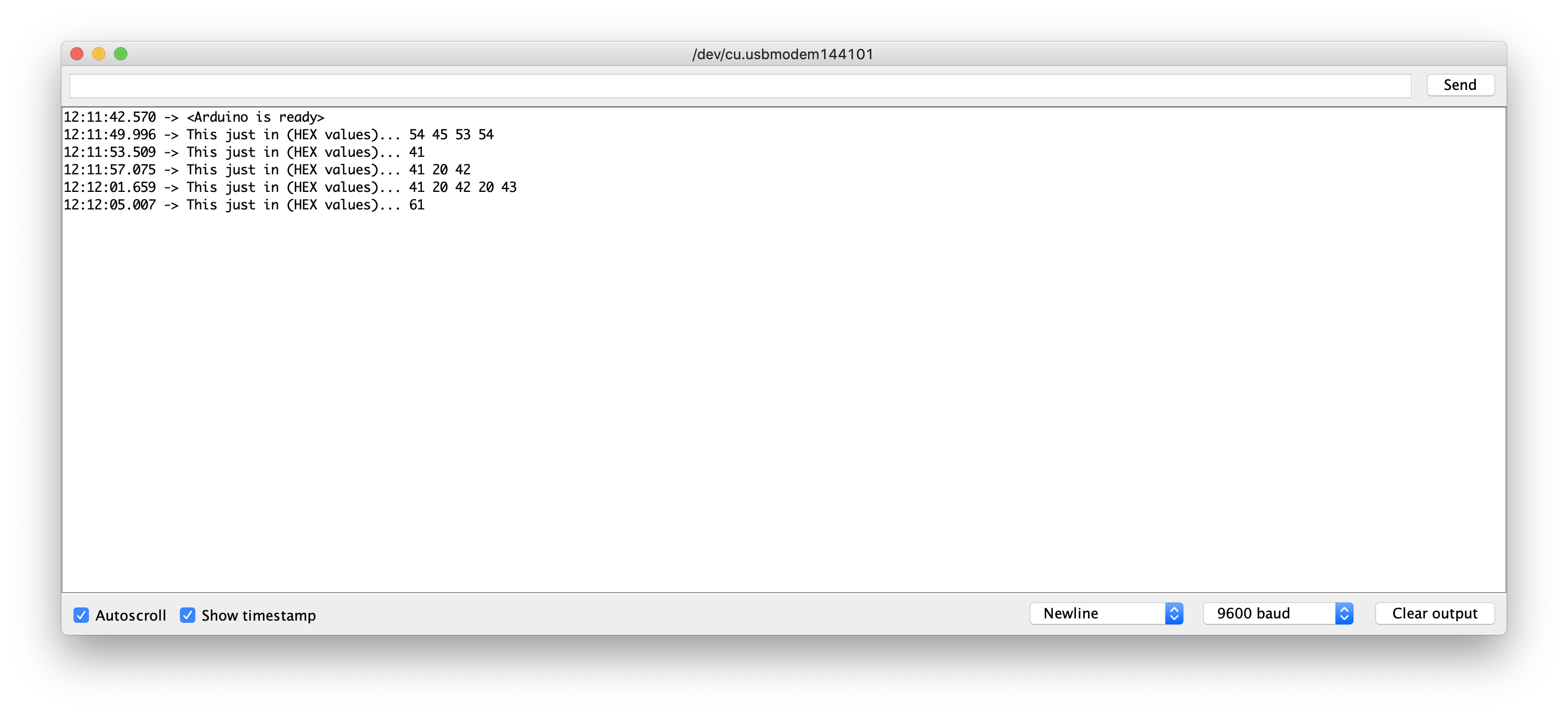
Example 6: Program to Receive Binary Data
#include <Arduino.h>

const byte numBytes = 32;
byte receivedBytes[numBytes];
byte numReceived = 0;

boolean newData = false;


void recvBytesWithStartEndMarkers();
void showNewData();
void setup() {
    Serial.begin(9600);
    Serial.println("<Arduino is ready>");
}

void loop() {
    recvBytesWithStartEndMarkers();
    showNewData();
}

void recvBytesWithStartEndMarkers() {
    static boolean recvInProgress = false;
    static byte ndx = 0;
    byte startMarker = 0x3C;
    byte endMarker = 0x3E;
    byte rb;


    while (Serial.available() > 0 && !newData) {
        rb = Serial.read();

        if (recvInProgress) {
            if (rb != endMarker) {
                receivedBytes[ndx] = rb;
                ndx++;
                if (ndx >= numBytes) {
                    ndx = numBytes - 1;
                }
            }
            else {
                receivedBytes[ndx] = '\0'; // terminate the string
                recvInProgress = false;
                numReceived = ndx;  // save the number for use when printing
                ndx = 0;
                newData = true;
            }
        }

        else if (rb == startMarker) {
            recvInProgress = true;
        }
    }
}

void showNewData() {
    if (newData) {
        Serial.print("This just in (HEX values)... ");
        for (byte n = 0; n < numReceived; n++) {
            Serial.print(receivedBytes[n], HEX);
            Serial.print(' ');
        }
        Serial.println();
        newData = false;
    }
}
Arduino Serial Examples
Arduino Read HEX from Serial
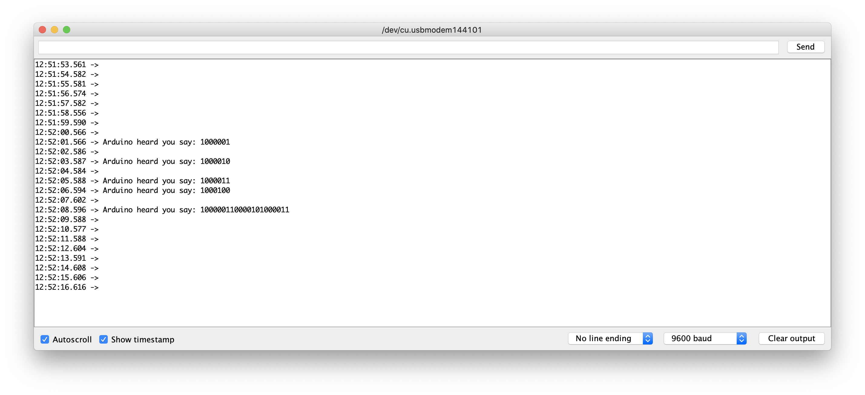
Simple Serial Read
serialRead() reads one byte at a time from the serial buffer, so in order to print out the whole sentence at once (it is actually still printing one byte at a time but the pc will receive it not interupted by newLines or other printString inside you loop) you must loop untill there are bytes in the serial buffer and and print right away that byte you just read. After that the loop can continue it’s tasks.
#include "Arduino.h"

int serIn; // var that hold the bytes in read from the serialBuffer.
void setup(){
    Serial.begin(9600);
}

void loop(){
    // simple feedback from Arduino Serial.println("Hello, World!")
    // only if there are bytes in the serial buffer execute the following code
    if (Serial.available()){
        // inform that Arduino heard you saying something
        Serial.print("Arduino heard you say: ");
        // keep reading and printing from serial until there are bytes in the serial buffer
        while (Serial.available()>0){
            serIn = Serial.read(); // read Serial
            Serial.print(serIn, BIN); // prints the character just read
        }
    }
    // the serial buffer is over just go to the line (or pass your favorite stop char)
    Serial.println();
    delay(1000);
}
Arduino Parse HEX
C/C++ Logic
Read and Parse Hex in CPP
Read and Parse Hex in C
Python Logic
https://github.com/blackdog70/mm485
AlfaSat Communication Protocol (ACP)
ACP Frame
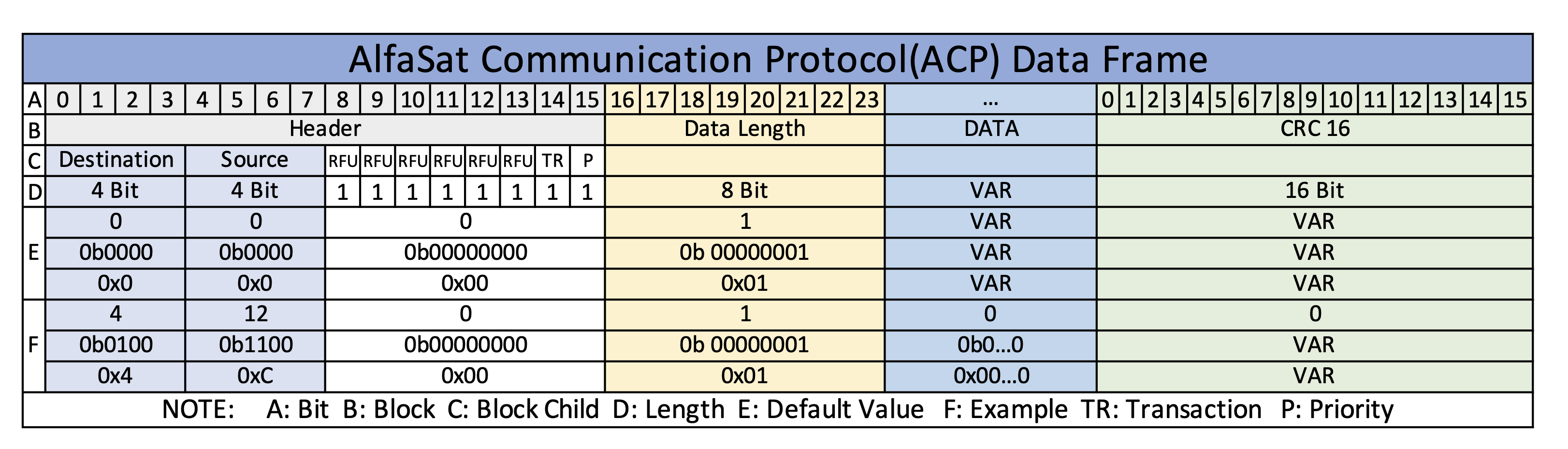
ACP Node Address
| DEC | BIN | HEX | ID | DESCRIPTION |
|---|---|---|---|---|
| 0 | 0b 0000 | 0x 00 | OBC | On Board Computer |
| 1 | 0b 0001 | 0x 01 | EPS | Energy Power System |
| 2 | 0b 0010 | 0x 02 | TRX | Telecommunication |
| 3 | 0b 0011 | 0x 03 | TOP | Top Board |
| 4 | 0b 0100 | 0x 04 | SB | Sensorboard |
| … | … | … | … | … |
| … | … | … | … | … |
| 12 | 0b 1100 | 0x 0C | GS_HW | Groundstation Hardware |
| 13 | 0b 1101 | 0x 0D | GS_PC | Groundstation Computer |
ACP OBC Commands
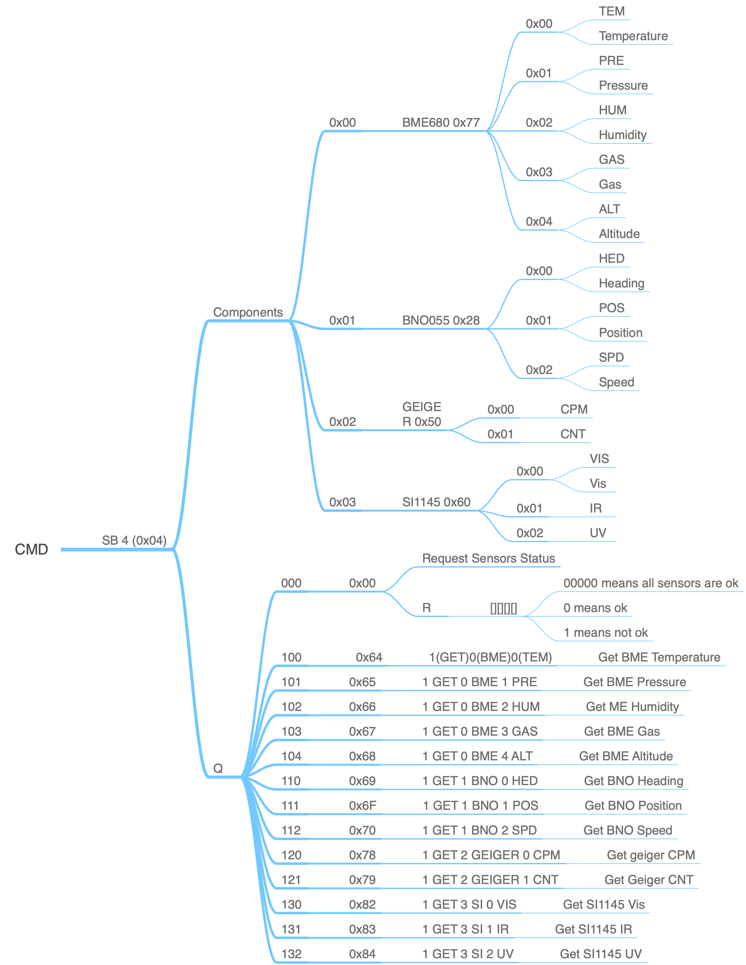
ACP Sensorboard Querry Commands
| DEC | HEX | CMD ID | CMD TYPE | TARGET ID | VAR ID | DESCRIPTION |
|---|---|---|---|---|---|---|
| 0 | 0x00 | STAT | CHECK | SB | SENSORS | Check sensors status |
| 100 | 0x64 | BMET | GET | BME | TEM | Get BME temperature |
| 101 | 0x65 | BMEP | GET | BME | PRE | Get BME pressure |
| 102 | 0x66 | BMEH | GET | BME | HUM | Get BME humidity |
| 103 | 0x67 | BMEG | GET | BME | GAS | Get BME gas |
| 104 | 0x68 | BMEA | GET | BME | ALT | Get BME altitude |
| 110 | 0x69 | BNOH | GET | BNO | HED | Get BNO Heading |
| 111 | 0x6F | BNOP | GET | BNO | POS | Get BNO Position |
| 112 | 0x70 | BNOS | GET | BNO | SPD | Get BNO Speed |
| 120 | 0x78 | GGC | GET | GG | CPM | Get Geiger CPM |
| 121 | 0x79 | RFU | RFU | RFU | RFU | RFU |
| 130 | 0x82 | SIV | GET | SI | VIS | Get SI VIS |
| 131 | 0x83 | SIR | GET | SI | IR | Get SI IR |
| 132 | 0x84 | SUV | GET | SI | UV | Get SI UV |
ACP Sensorboard Response Data Definitions
Types reference in C& C++ :
| Signed Type | Unsigned Type | Description |
|---|---|---|
| int8_t | uint8_t | Integer type with a width of exactly 8, 16, 32, or 64 bits. For signed types, negative values are represented using 2’s complement. No padding bits. Optional: These typedefs are not defined if no types with such characteristics exist.* |
| int16_t | uint16_t | SAME |
| int32_t | uint32_t | SAME |
Type range in AlfaSat (NOT YET CONFIRMED):
| Representing Integer (unsigned 8 bit) uint8 | ||||||||
|---|---|---|---|---|---|---|---|---|
| bit | 2^7 | 2^6 | 2^5 | 2^4 | 2^3 | 2^2 | 2^1 | 2^0 |
| val | 128 | 64 | 32 | 16 | 8 | 4 | 2 | 1 |
| max-until | 255 | 127 | 63 | 31 | 15 | 7 | 3 | 1 |
| bits | ||||||||
| range | 0 ~ 255 |
| Representing Integer (signed 8 bit) int8 | ||||||||
|---|---|---|---|---|---|---|---|---|
| bit | 2^6 | 2^5 | 2^4 | 2^3 | 2^2 | 2^1 | 2^0 | SIGN |
| val | 64 | 32 | 16 | 8 | 4 | 2 | 1 | 0/1 |
| max-until | 127 | 63 | 31 | 15 | 7 | 3 | 1 | 0/1 |
| bits | 0/1 | |||||||
| range | -127 ~ 0 ~ 127 |
| Representing Integer (unsigned 16 bit) uint16 | ||||||||||||||||
|---|---|---|---|---|---|---|---|---|---|---|---|---|---|---|---|---|
| bit | 2^15 | 2^14 | 2^13 | 2^12 | 2^11 | 2^10 | 2^9 | 2^8 | 2^7 | 2^6 | 2^5 | 2^4 | 2^3 | 2^2 | 2^1 | 2^0 |
| val | 32768 | 16384 | 8192 | 4096 | 2048 | 1024 | 512 | 256 | 128 | 64 | 32 | 16 | 8 | 4 | 2 | 1 |
| max-until | 65535 | 32767 | 16383 | 8191 | 4095 | 2047 | 1023 | 511 | 255 | 127 | 63 | 31 | 15 | 7 | 3 | 1 |
| bits | ||||||||||||||||
| range | 0 ~ 65535 |
| Representing Integer (signed 16 bit) int16 | ||||||||||||||||
|---|---|---|---|---|---|---|---|---|---|---|---|---|---|---|---|---|
| bit | 2^14 | 2^13 | 2^12 | 2^11 | 2^10 | 2^9 | 2^8 | 2^7 | 2^6 | 2^5 | 2^4 | 2^3 | 2^2 | 2^1 | 2^0 | SIGN |
| val | 16384 | 8192 | 4096 | 2048 | 1024 | 512 | 256 | 128 | 64 | 32 | 16 | 8 | 4 | 2 | 1 | 0/1 |
| max-until | 32767 | 16383 | 8191 | 4095 | 2047 | 1023 | 511 | 255 | 127 | 63 | 31 | 15 | 7 | 3 | 1 | 0/1 |
| bits | 0/1 | |||||||||||||||
| range | -32767 ~ 0 ~ 32767 |
FOR FLOAT PRECISION =2
So, 1123.23 == 112323
Integer Data Types
| C type | stdint.h type | Bits | Sign | Range |
|---|---|---|---|---|
| char | uint8_t | 8 | Unsigned | 0 .. 255 | 2.55 |
| signed char | int8_t | 8 | Signed | -128 .. 127 | 1.27 +- |
| unsigned short | uint16_t | 16 | Unsigned | 0 .. 65,535 | 655.35 |
| short | int16_t | 16 | Signed | -32,768 .. 32,767 | 32.767 +- |
| unsigned int | uint32_t | 32 | Unsigned | 0 .. 4,294,967,295 | 42949672. 95 |
| int | int32_t | 32 | Signed | -2,147,483,648 .. 2,147,483,647 |
| unsigned long long | uint64_t | 64 | Unsigned | 0 .. 18,446,744,073,709,551,615 |
| long long | int64_t | 64 | Signed | -9,223,372,036,854,775,808 .. 9,223,372,036,854,775,807 |
| Dfor | Parameter | Min | Max | Unit | Dtype | Exp | Exp.HEX | LEN | NOte |
|---|---|---|---|---|---|---|---|---|---|
| 0x00 | Status | 0 | 15 | Boolean | char [4] |
0b1111 | 0x0F | 1 byte | Int |
| 0x64 | Temperature | -40.0 | 85.00 | °C | uint16 | 31.09 | 0xC25 | 2 byte | Float |
| Pressure | 300.0 | 1100.00 | hPa | unit32 | 917.44 | 0x16660 | 4 byte | Float | |
| Humidity | 0.00 | 100.00 | % | uint32 | 19.59 | 0x7A7 | 4 byte | Float | |
| Gas | 0.00 | 100.00 | KOhms | uint32 | 32.76 | 0xCCC | 4 byte | Float | |
| Altitude | 0.00 | 30000.00 | m | uint32 | 823.23 | 0x14193 | 4 byte | Float | |
| Heading | 0.00 | 360.00 | ° | uint16 | 355.63 | 2+2 | Float | ||
| Position(x,y) | 0.00 | 360.00 | ° | uint16 | 2+2 | Float | |||
| Speed | 0.00 | 100.00 | m/s | uint16 | 2+2 | Float | |||
| CPM | 0 | 500 | - | uint16 | 204 | 0xCC | 2 | Int | |
| VIS | 0 | 300 | - | uint16 | 262 | 0x106 | 2 | Int | |
| IR | 0 | 300 | - | uint16 | 258 | 0x102 | 2 | Int | |
| UV | 0.00 | 99.00 | - | uint16 | 1.03 | 0x67 | 2 | Float |